
Pack 5
BUILD INSTRUCTIONS
Advice from the experts
Spare screws are included with each part. Occasionally, you may be instructed to keep spare or unused screws for a later stage. Keep these spares in a safe place and label them correctly.
Please make sure you don’t mix up the screws. They look quite similar, but the threads do vary slightly. Using the wrong screws may damage the parts. Only use the correct size screwdriver that fits the screw head firmly.
When securing parts together using multiple screws, fit each screw loosely to ensure all the parts are correctly aligned before gently tightening them firmly, but not overtight, in the order in which you placed them.
The screwdriver can be magnetized by stroking it with a magnet (fridge magnet, etc.) enabling it to hold the screws and make assembly easier.
If a screw is tight going into a metal part, do not force it as you may shear the head off. Remove it and put a tiny smear of Vaseline, soap or light oil on the thread. That will lubricate it and make it easier to tighten.
Some parts will require a little glue for assembly. Please apply glue sparingly and use a cocktail stick so that you don’t use too much nor apply the glue too heavily. We recommend superglue gel or Extra Thin Liquid modeling glue. Where possible, parts should be test-fitted in place before gluing.
Make sure you have good ventilation when using adhesives and to replace caps firmly.
Use a magnet to help find screws that have fallen on the floor.
Use masking tape to hold parts temporarily in place.
Cut parts from a sprue (framework) with side cutters or a craft knife. Side cutters tend to be easiest.
During the course of this build, you will receive many pieces that you will assemble immediately – following the instructions in the corresponding stage – and other pieces that you should store safely to one side, for use in future assembly stages.
Always protect the paint finish on components by placing a cutting mat, sheet of white paper or soft cloth on your work surface.
When plugging cables in, ensure the power is switched off. Tweezers can be used to fit the PVC cables by gripping carefully around 5mm from the end of the cable. If a cable needs to be removed from a socket, do not pull on the cable as this could damage the connection. Grip the plug with tweezers to remove it.
Left and Right! When building your AH-64 Apache, the left- or right-hand side refers to that side as if you are sitting in the cockpit.
![]() When you see this symbol, pay attention to the instruction text in bold and check the orientation of the parts in the image as this will be particularly important for assembly in later stages.
When you see this symbol, pay attention to the instruction text in bold and check the orientation of the parts in the image as this will be particularly important for assembly in later stages.
WARNING: Some parts are assembled using magnets. These magnets can cause serious injury if they are swallowed. Keep away from children. If you suspect a magnet has been swallowed, seek medical help straight away.
This is not a toy. Not suitable for children under 14 years old due to small parts. Adult supervision required.
PARTS LIST
| 31-A | 31-H |
| 31-B | 31-J |
| 31-C | 31-K x4 |
| 31-D x2 | 31-L |
| 31-E x2 | BM x5 |
| 31-F x2 | CM x3 |
| 31-G x2 |

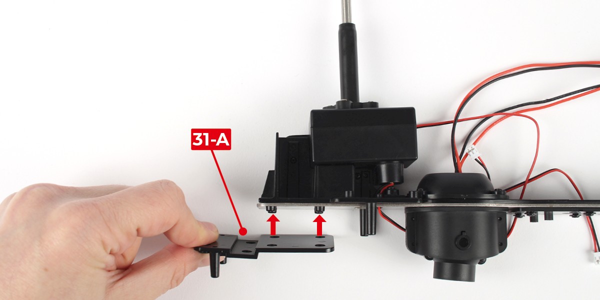
Step 1
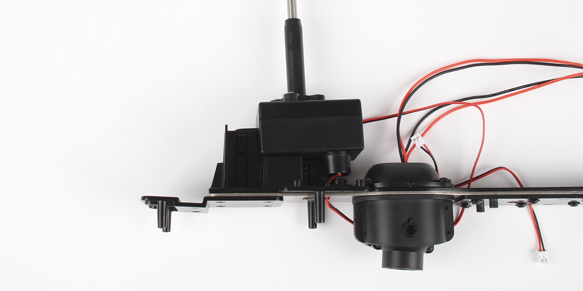
Press 31-A onto the main frame (stage 30).
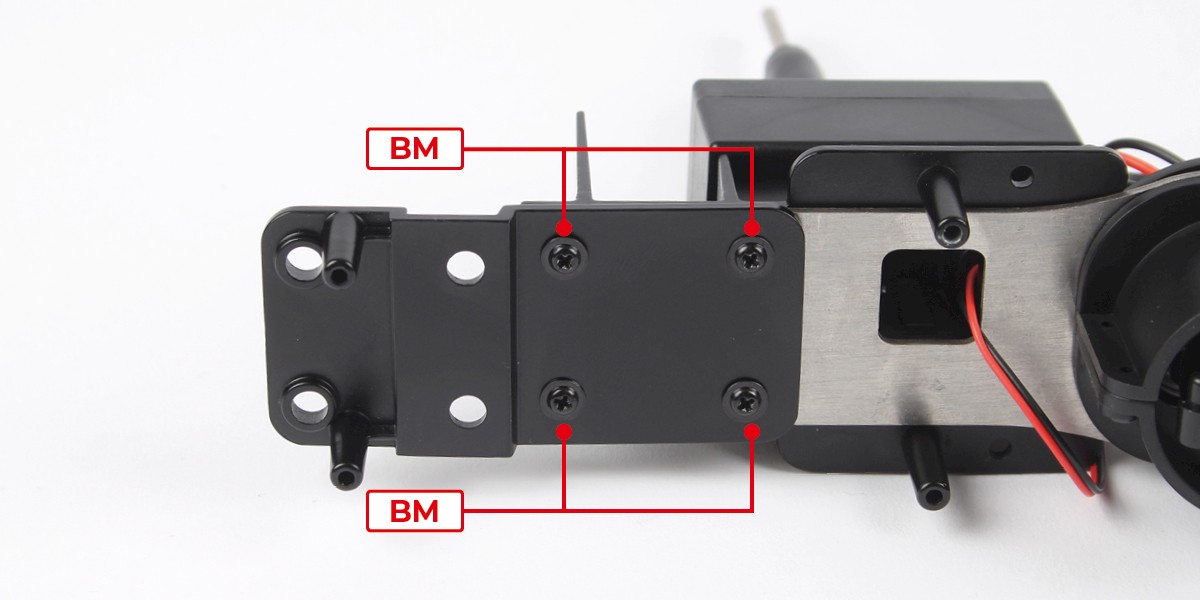
Step 2
Screw the parts together with 4x BM.
Step 3
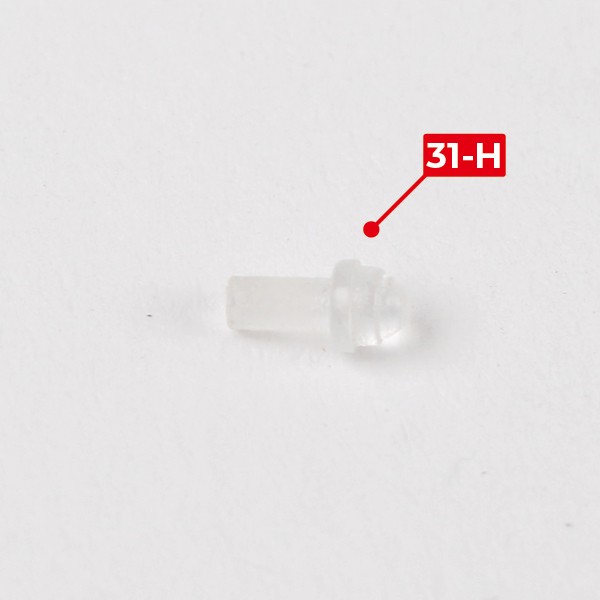
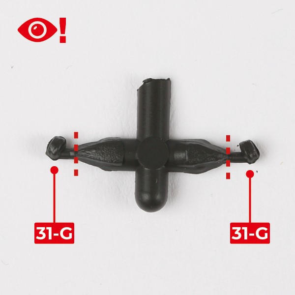
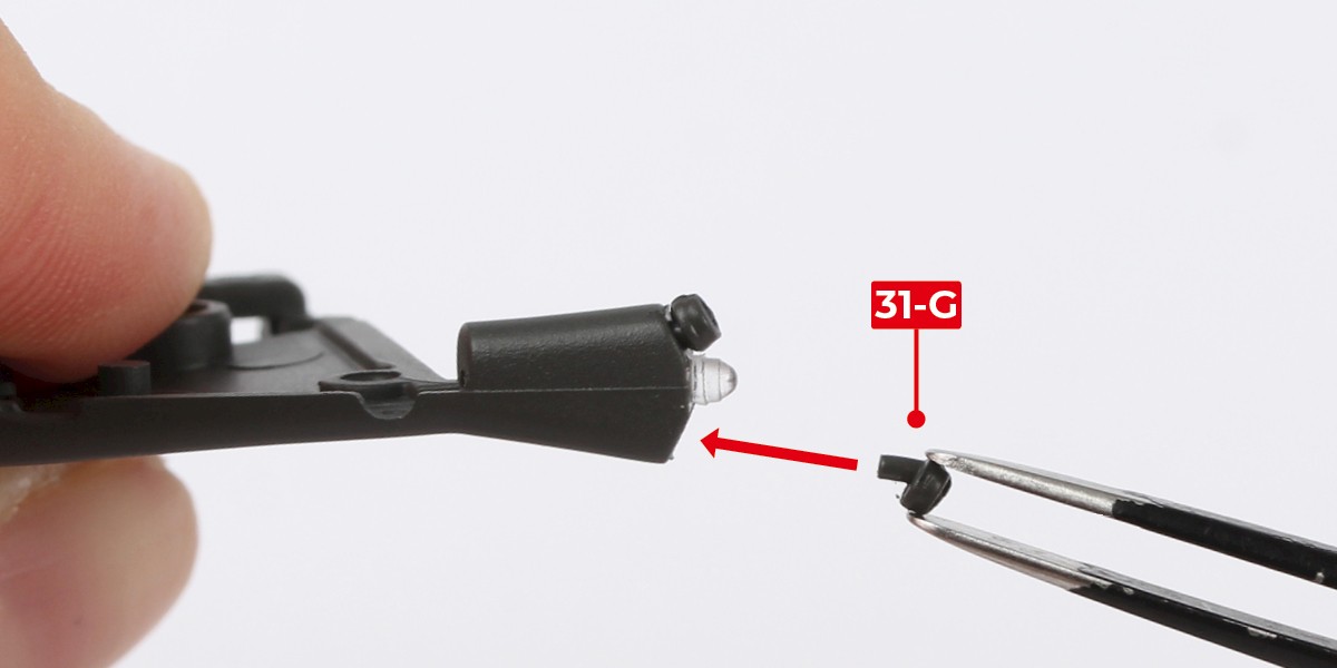
Take 31-H and the sprue for parts 31-G.
Cut 31-G from the sprue. Make sure to cut at the points indicated by the red lines.
Step 4
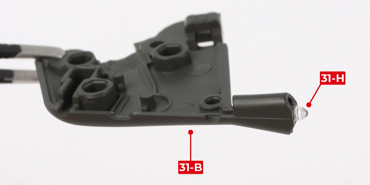
Glue 31-H to 31-B.
Step 5
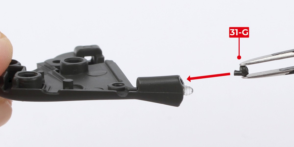
Glue 31-G to the assembly. Make sure the parts are oriented correctly.
Glue the second 31-G as shown.
Step 6
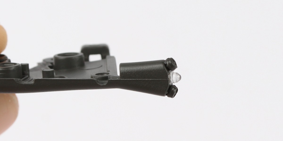
The assembly should look like this.
Step 7
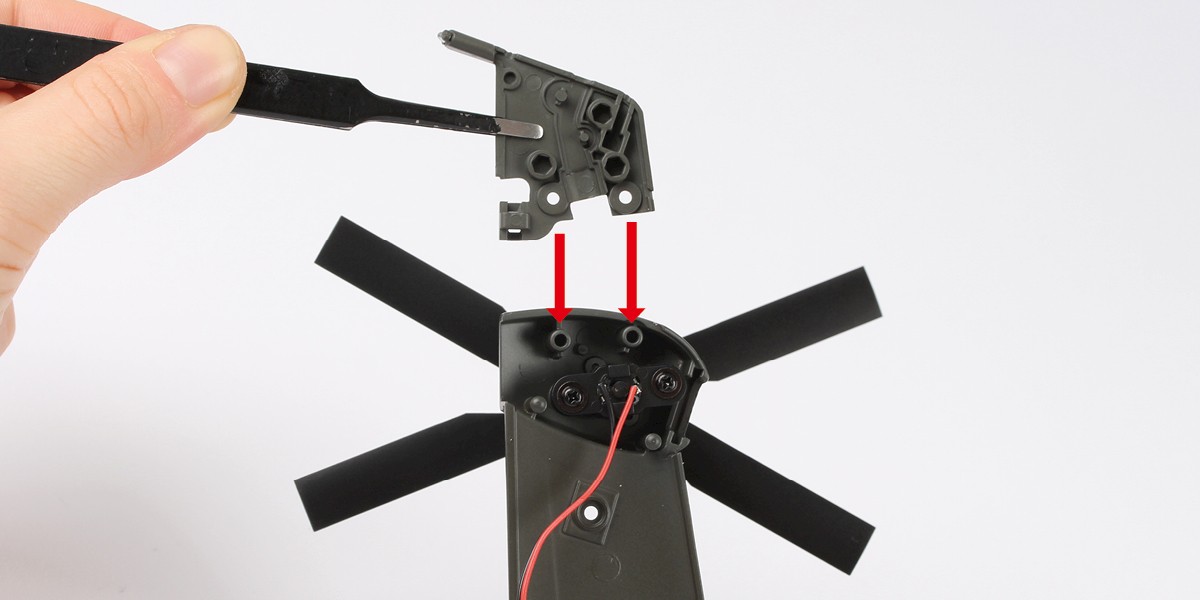
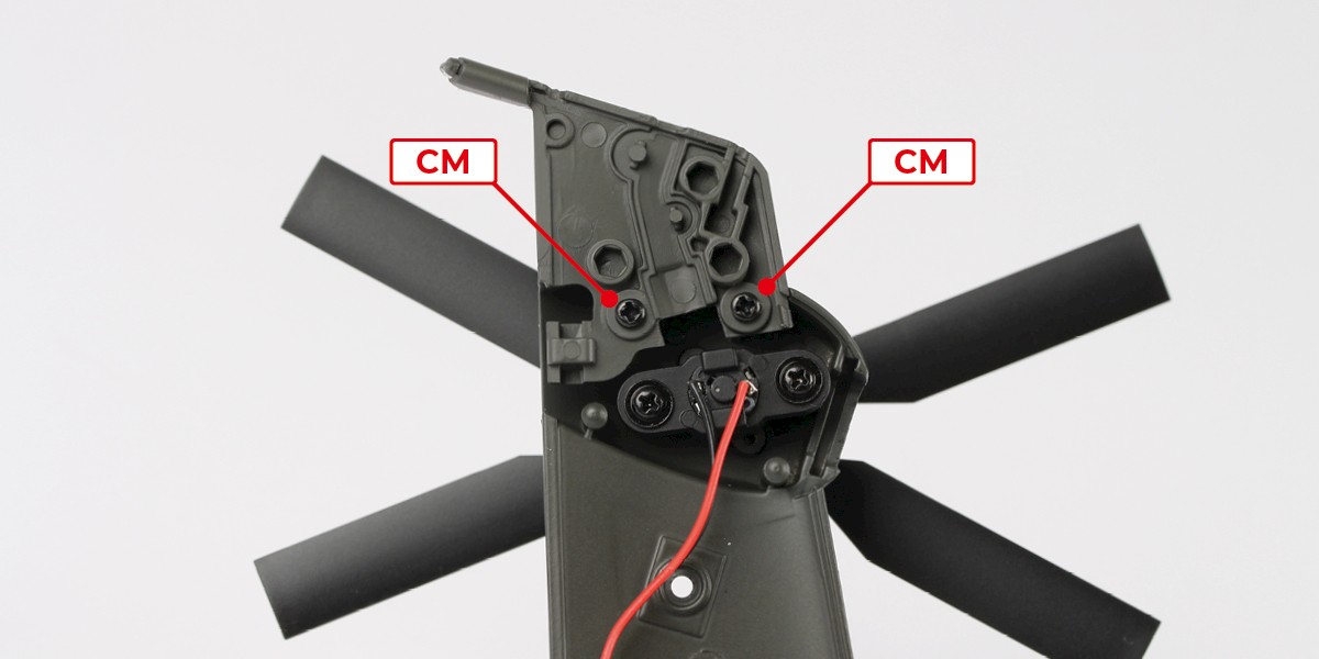
Fit the assembly onto the left tail fuselage (stage 02).
Screw the parts together with 2x CM.
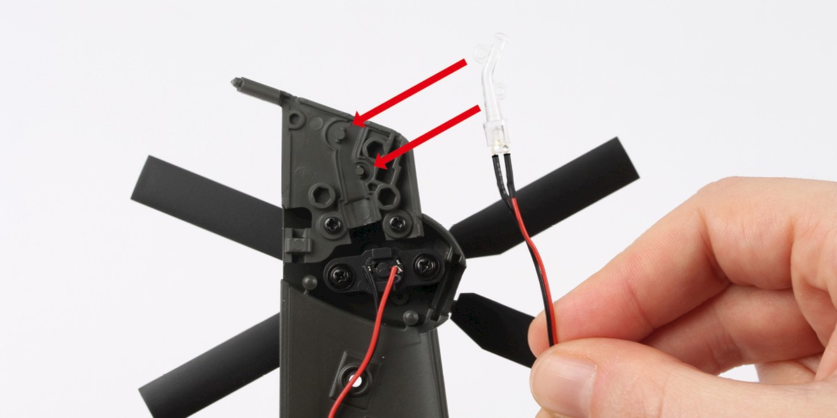
Step 8
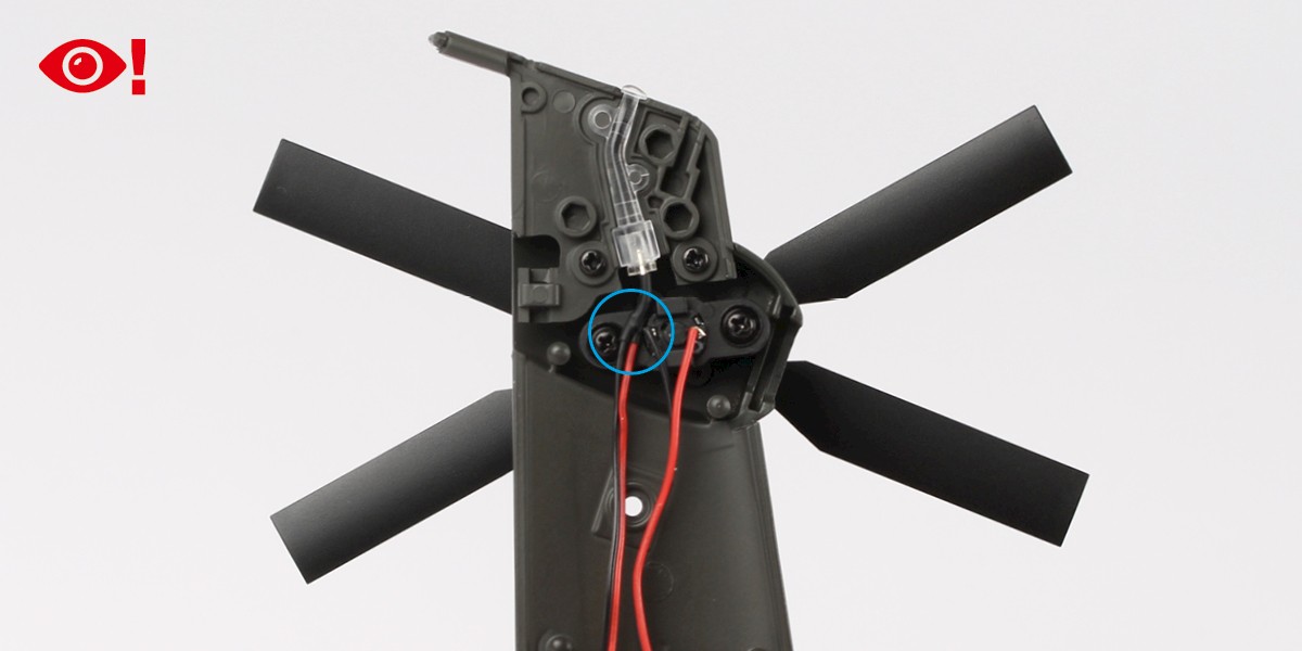
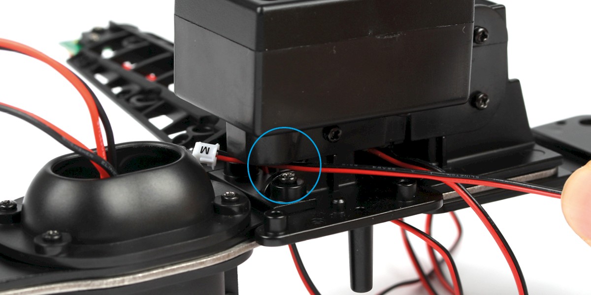
Press the top tail fin light (stage 01) onto the assembly.
You may need to bend the wire slightly to fit around the tail rotor motor (circled).
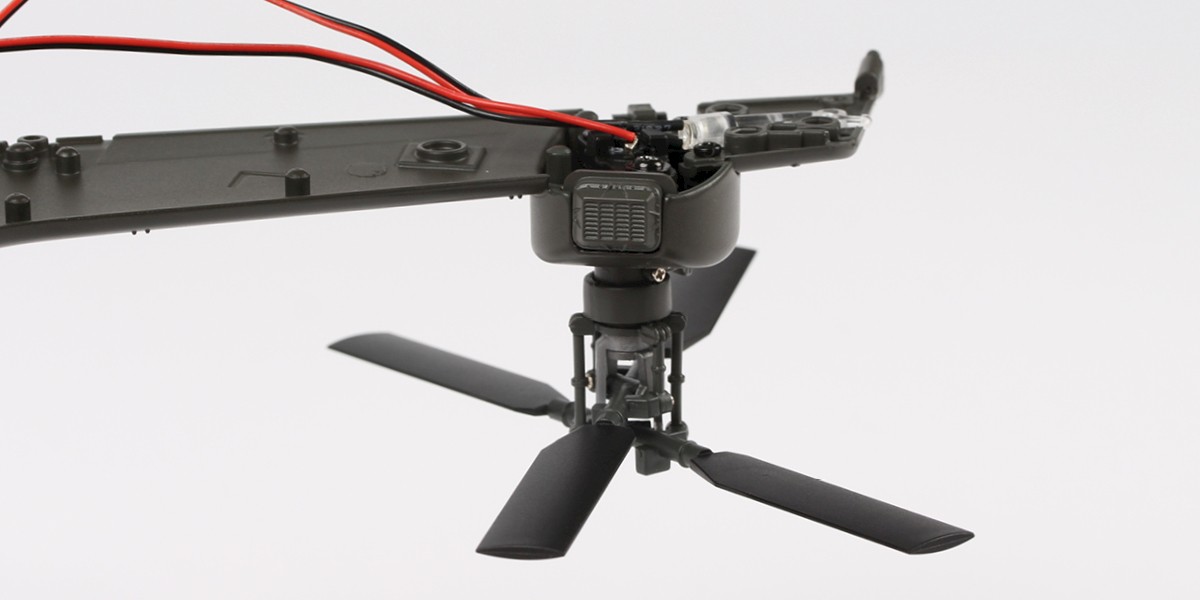
Step 9
Fit 31-C to the assembly.

Step 10
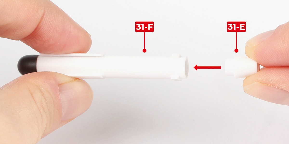
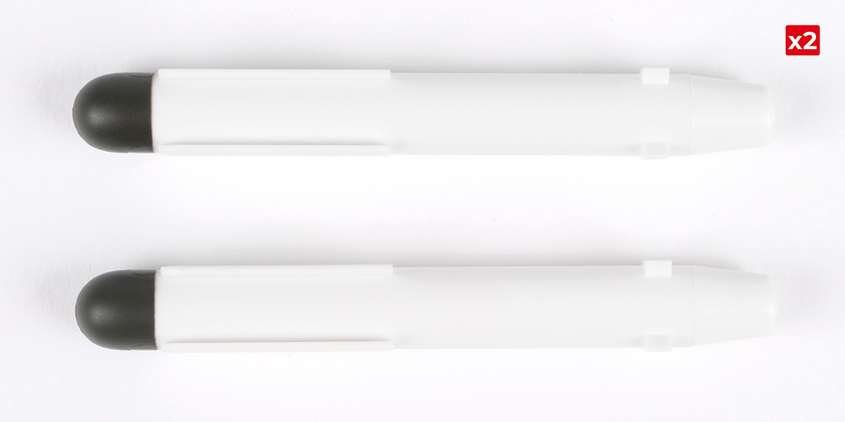
You will now start assembling the Spike missiles and their containers.
Fit 31-E into 31-F.
Repeat this process to assemble the second missile.
Step 11
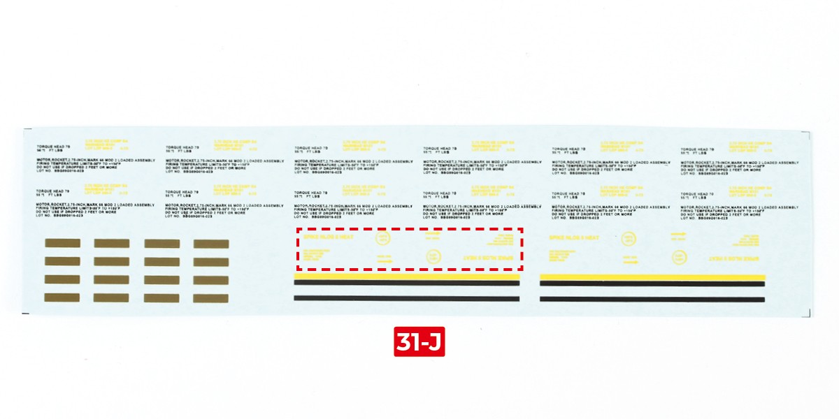
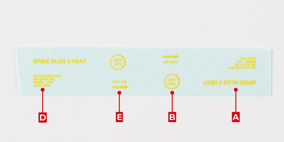
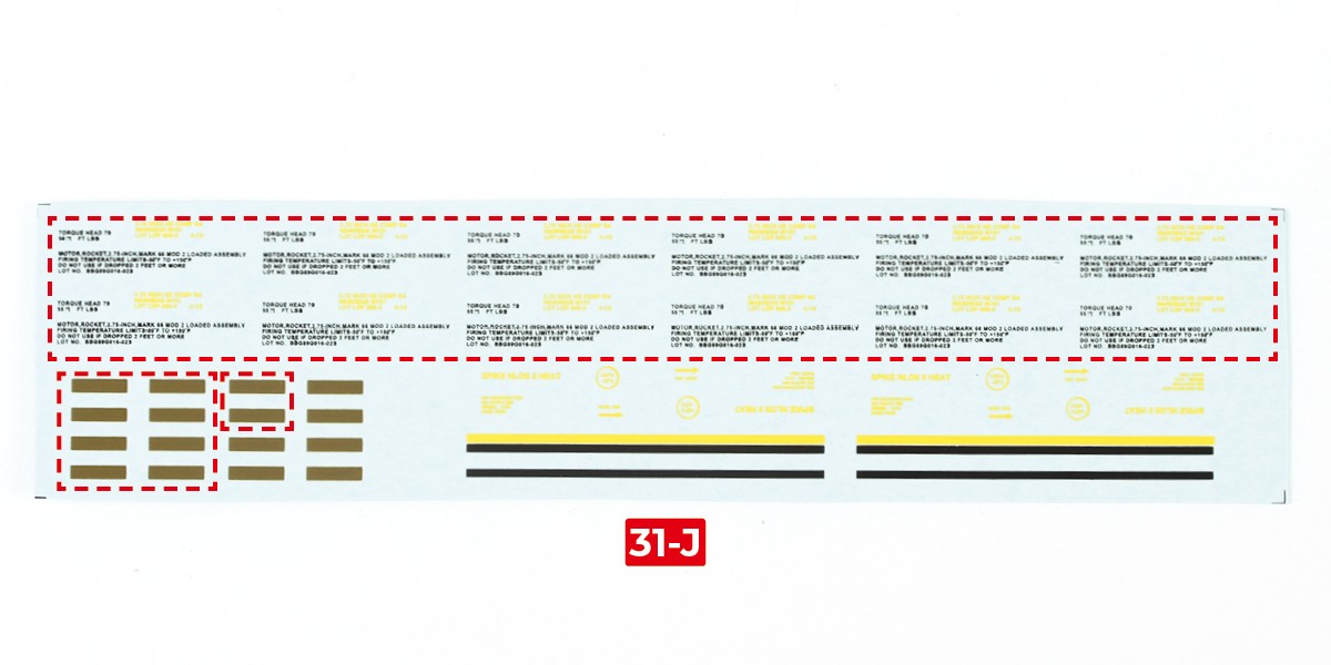
Cut the decals outlined in red from 31-J.
Step 12
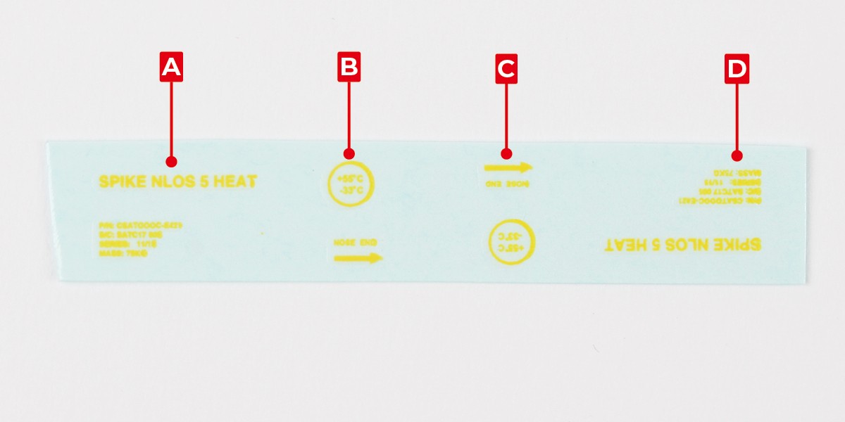
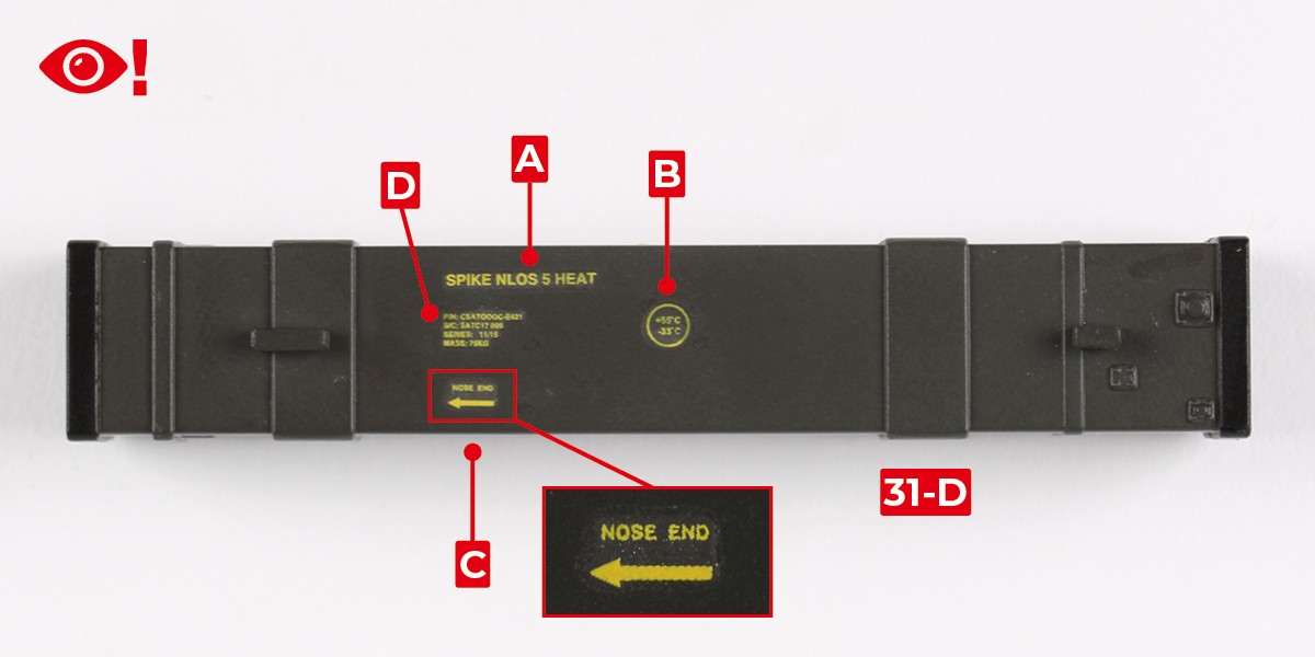
Apply decals A, B, C and D to 31-D.
Pay attention to decal C. The arrow should point left, with the text above the arrow.
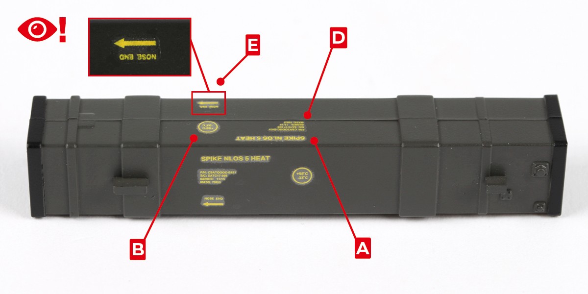
Step 13
Turn the assembly on its side with the previous set of decals facing you.
Apply decals A, B, D and E to 31-D. Note that these decals are applied with the text upside-down.
Step 14
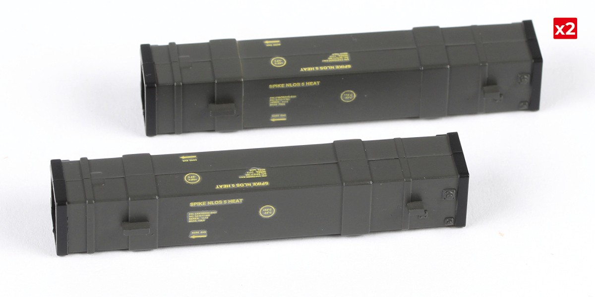
Repeat this process on the second missile container.
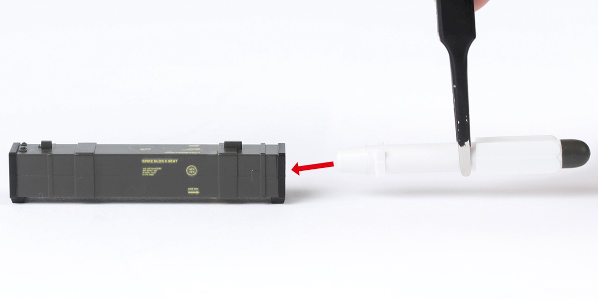
Step 15
The missiles can be placed inside the missile containers and displayed on the racks - parts 31-K.
Step 16
You will now apply the stripe decals to the Hellfire missiles. These decals replace those supplied in Packs 2 and 3.
Cut two decals F from 31-L.
Apply the decals to a missile from stage 11.
Step 17
Repeat this process to apply the decals to all the missiles from stages 11 and 16.
STAGE COMPLETE
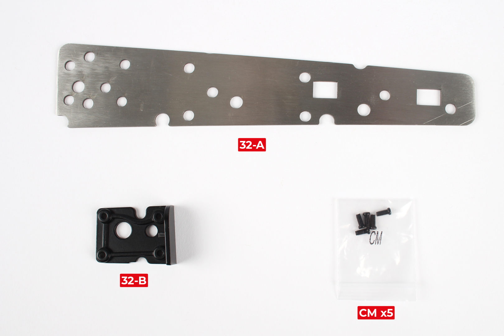
PARTS LIST
| 32-A | CM x5* |
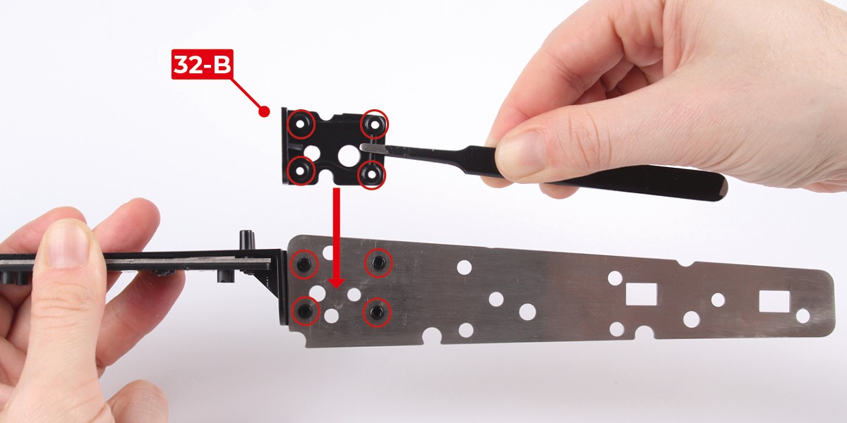
| 32-B |
*Use the CM screws provided with this stage, as they may be slightly different to the CM screws provided in Stage 30
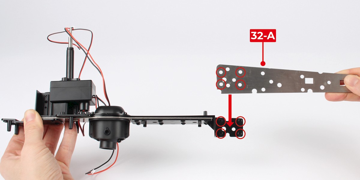
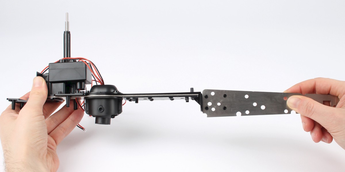
Step 1
Fit 32-A onto the main frame (stage 31).
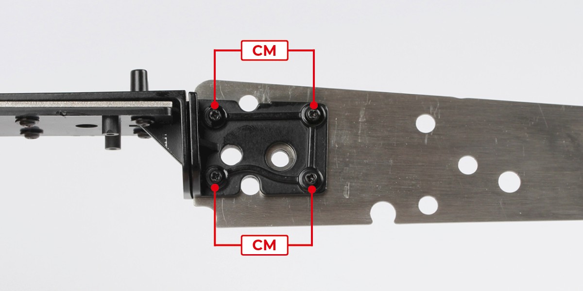
Step 2
Place 32-B onto 32-A then screw the parts together with 4x CM.
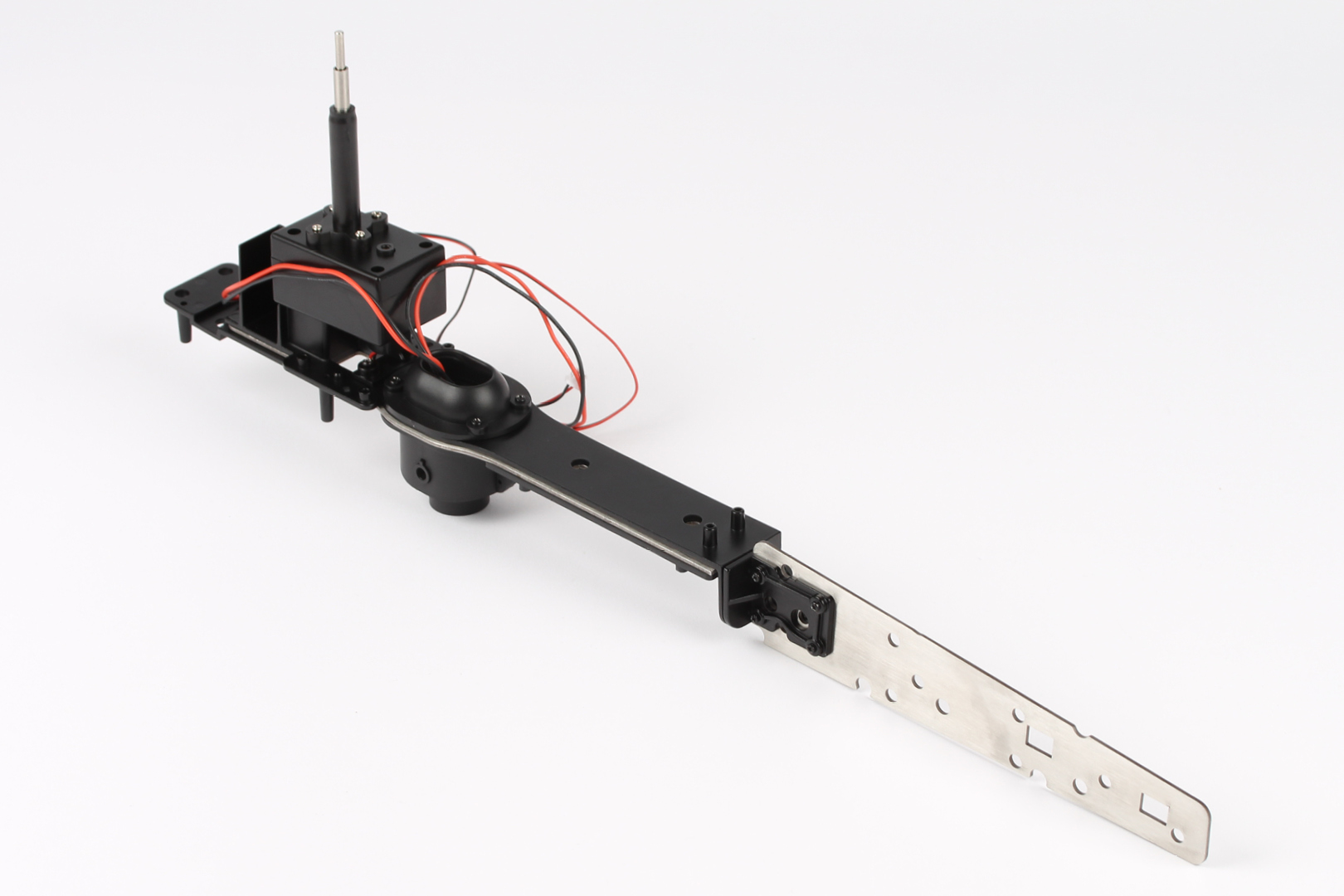
STAGE COMPLETE
PARTS LIST
| 33-A | CM x3 |
| 33-B | FP x3 |
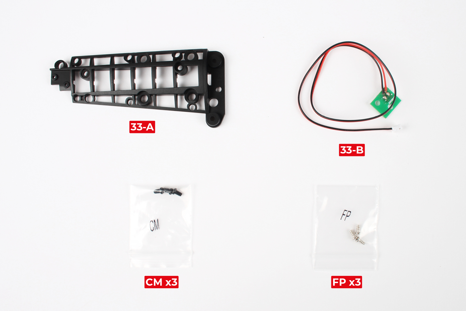
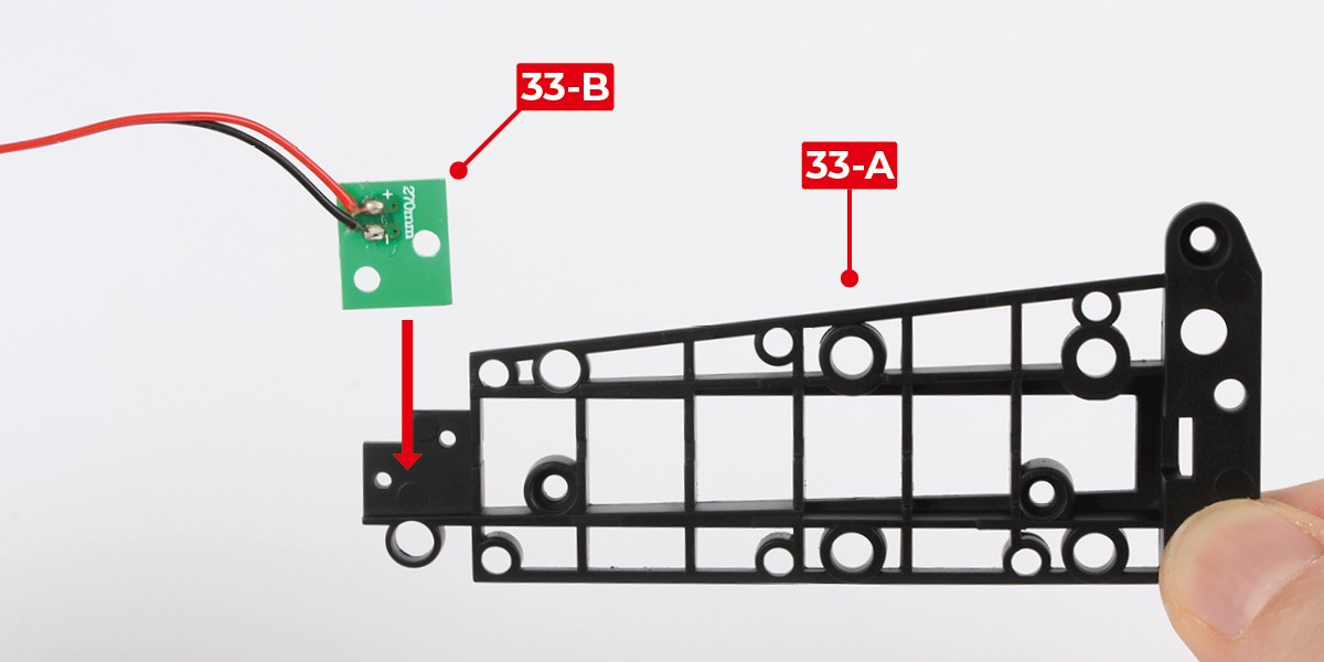
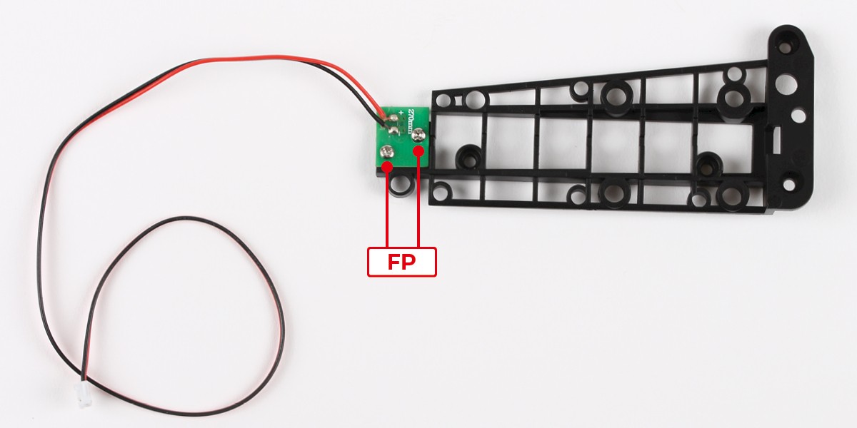
Step 1
Fit 33-B to 33-A.
Screw in place with 2x FP.
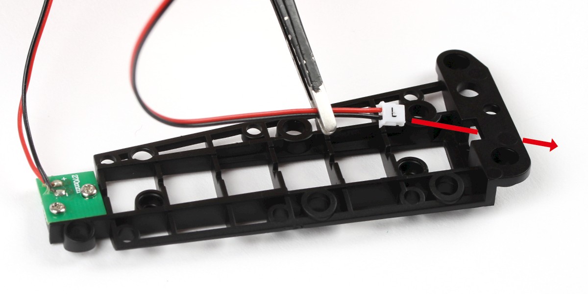
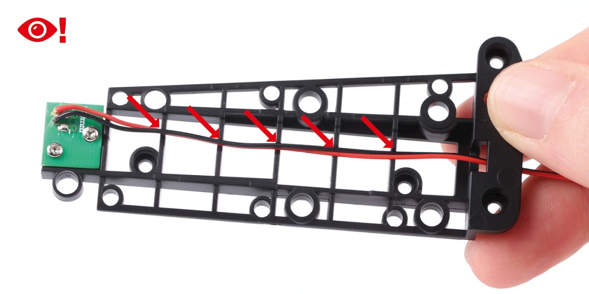
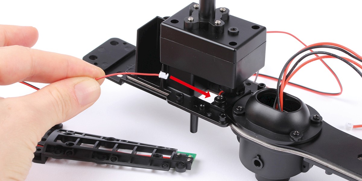
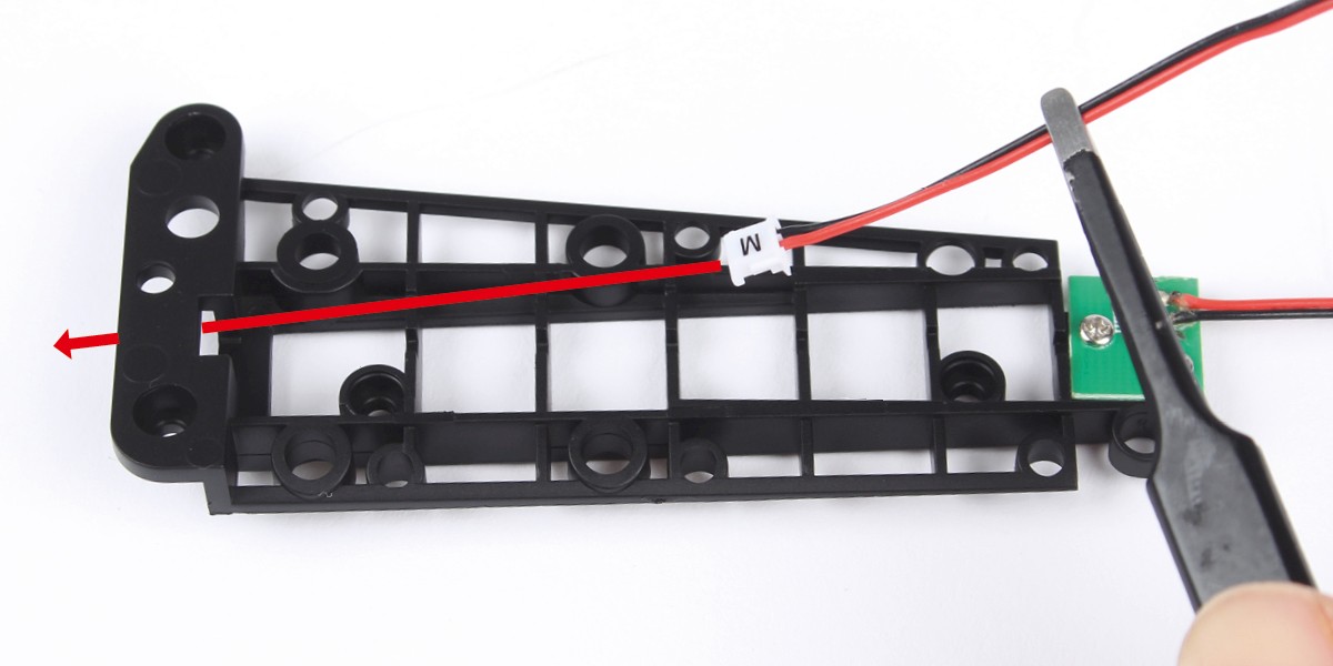
Step 2
Thread the cable through the opening.
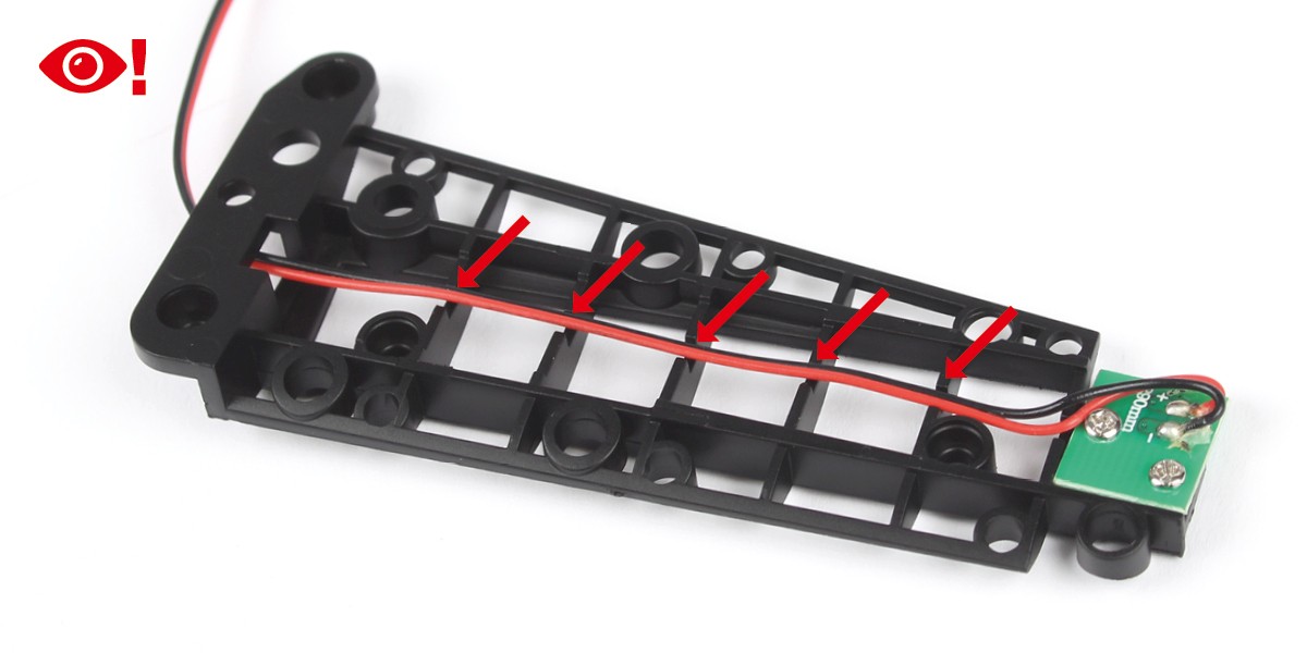
Press the cable into the recesses. Take care not to damage the connection when bending.
Step 3
Thread the cable through the opening in the main frame.
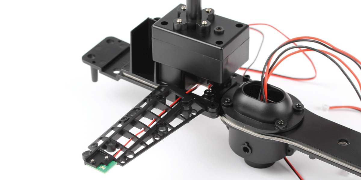
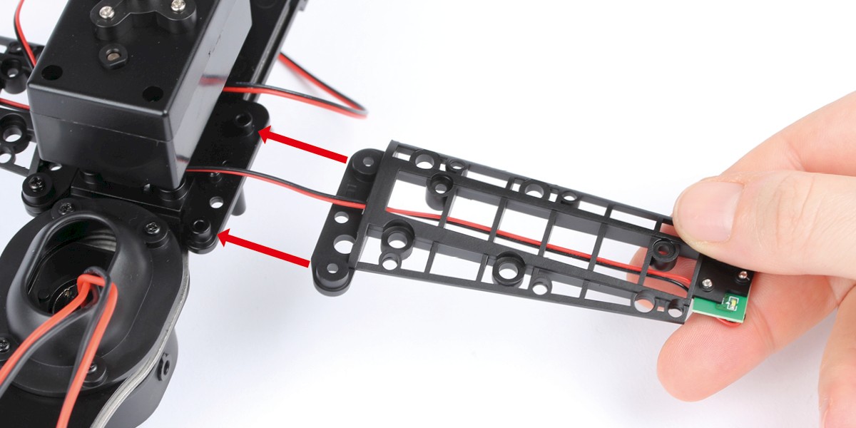
Step 4
Fit the assembly onto the main frame.
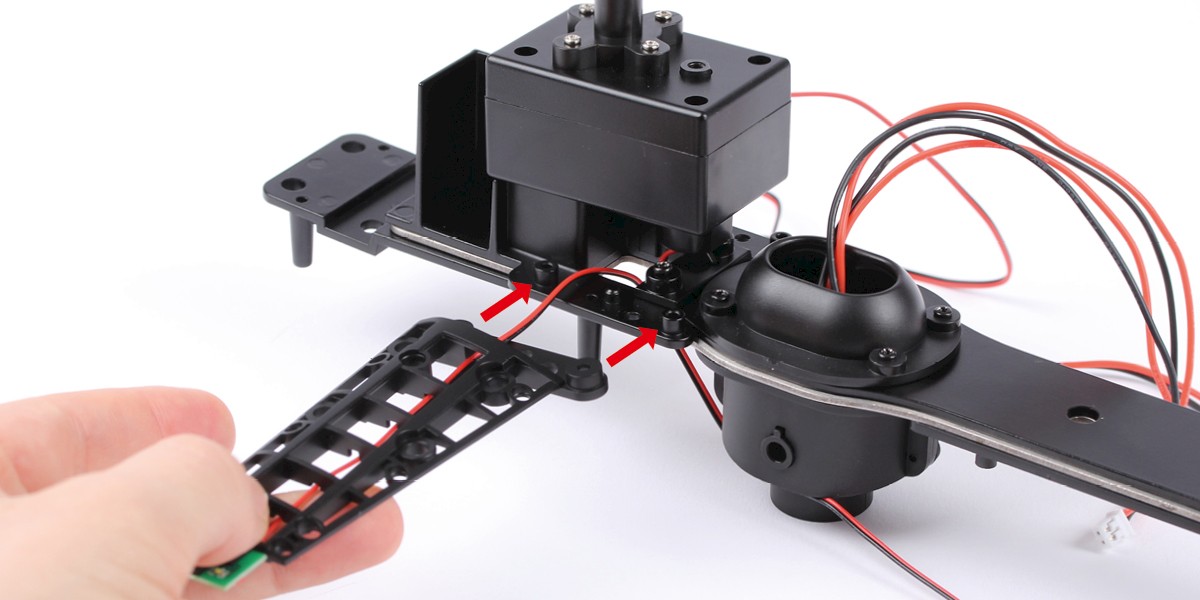
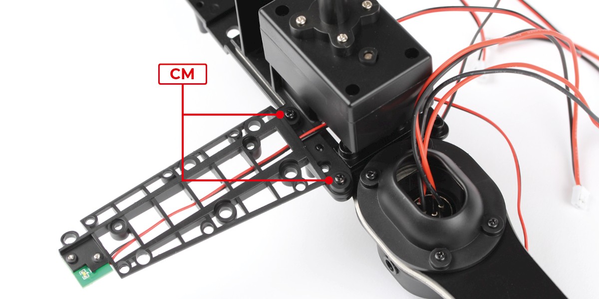
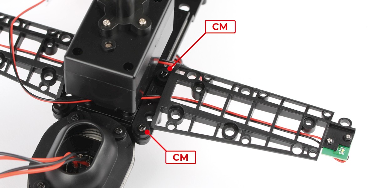
Step 5
Screw in place with 2x CM.
STAGE COMPLETE
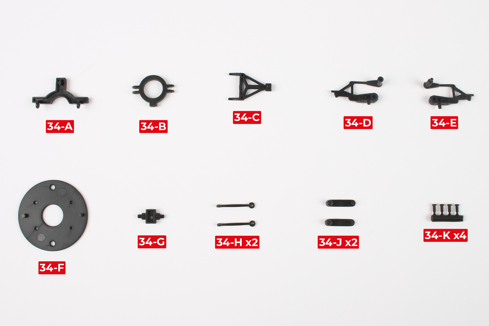
PARTS LIST
| 34-A | 34-F |
| 34-B | 34-G |
| 34-C | 34-H x2 |
| 34-D | 34-J x2 |
| 34-E | 34-K x4 |
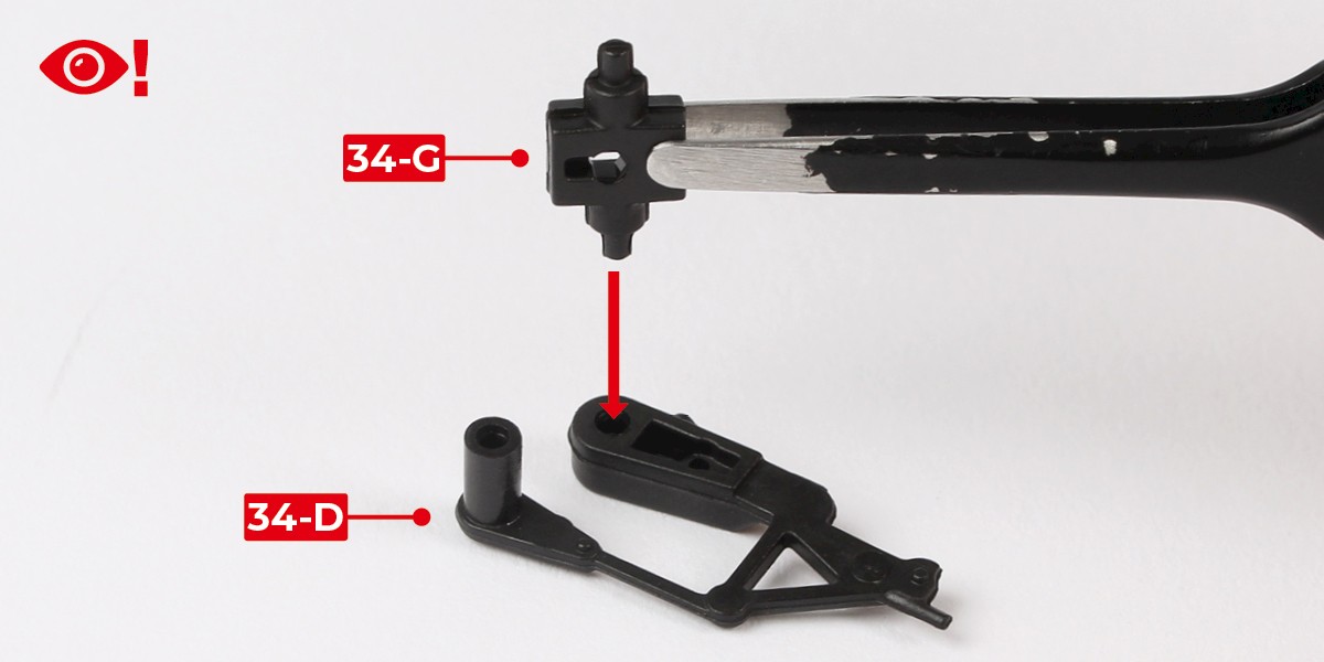
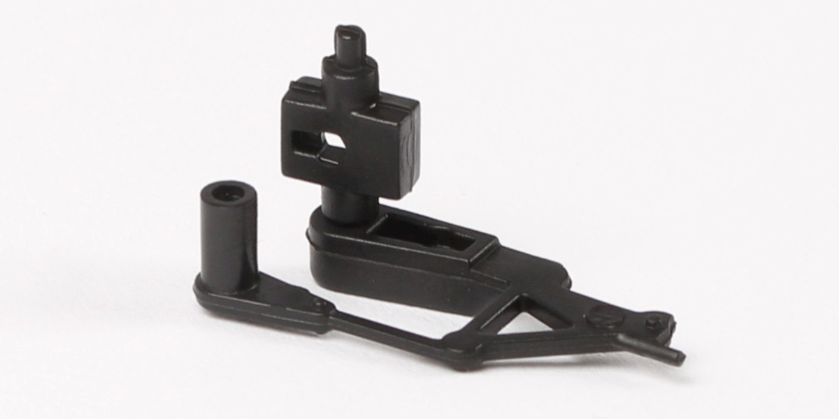
Step 1
Press 34-G into 34-D.
Make sure 34-G is oriented the correct way.
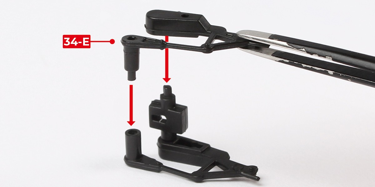
Step 2
Press 34-E onto the assembly.
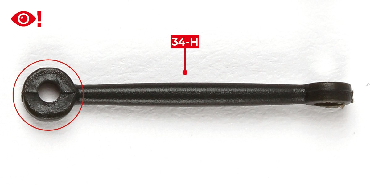
Step 3
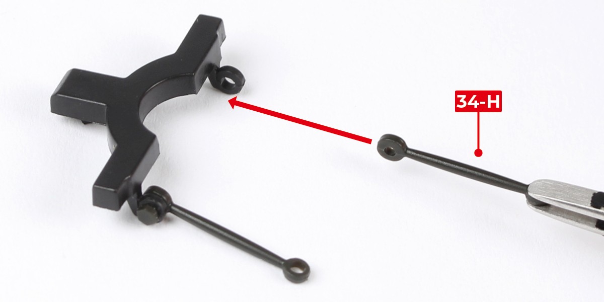
Note that one end of 34-H is thin and the other is thick.
Use the thick end (circled) for steps 4–8.
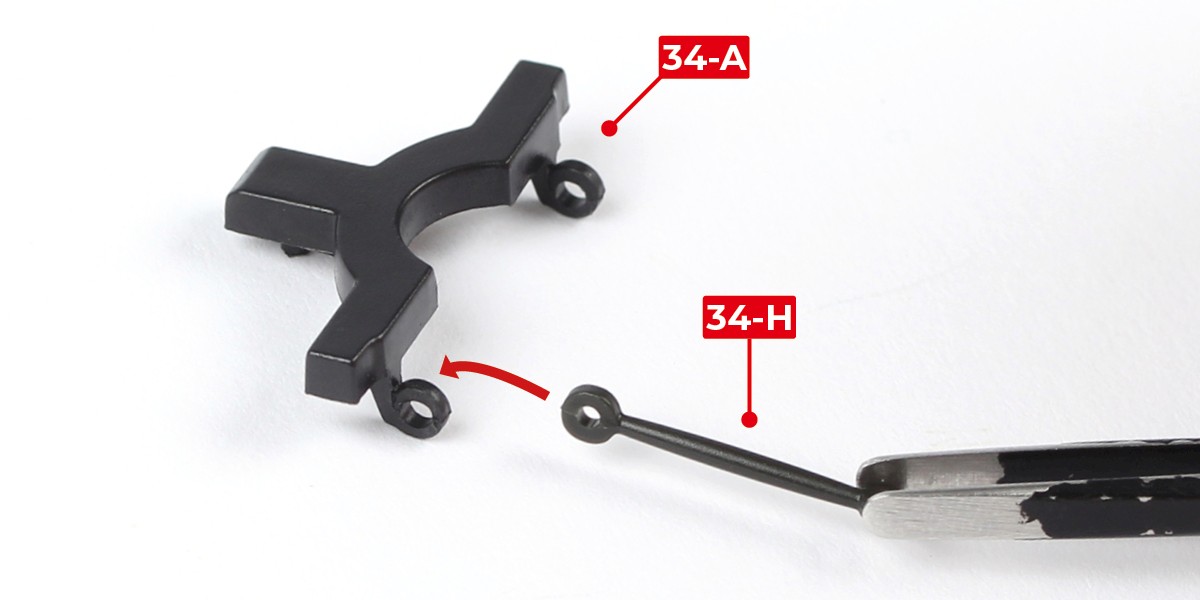
Step 4
Place 34-H on the inner side of 34-A as shown.
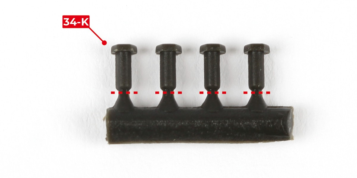
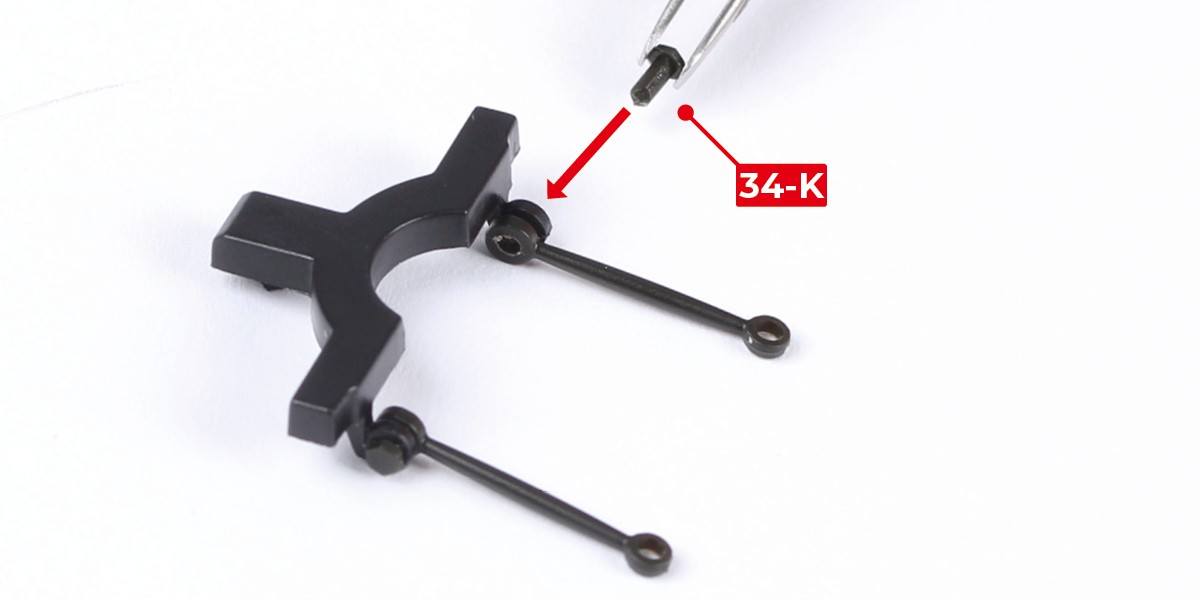
Step 5
Cut 34-K from the sprue as indicated by the dashed lines.
Step 6
Push 34-K through 34-A and into 34-H.
Step 7
Fit the remaining 34-H to the opposite side in the same way, securing it in place with 34-K.
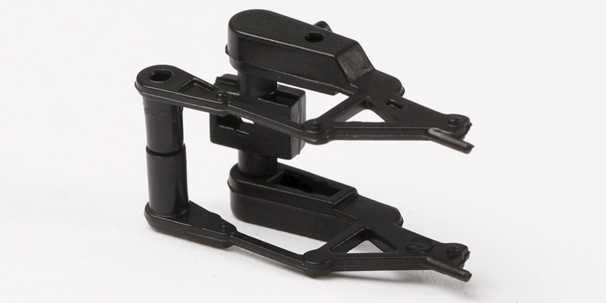
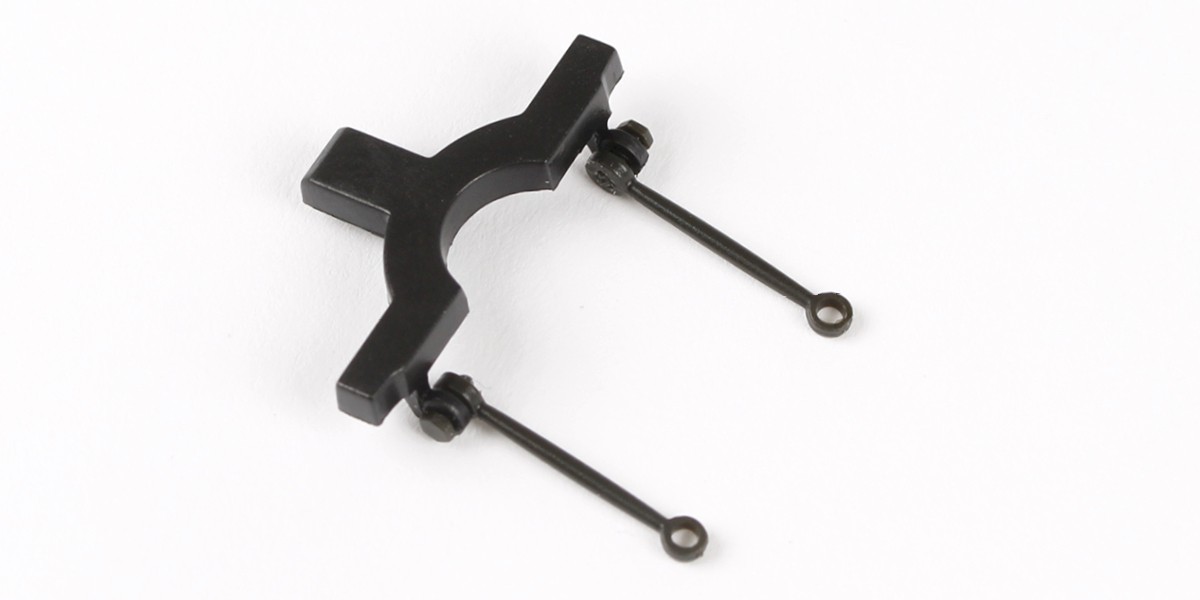
Step 8
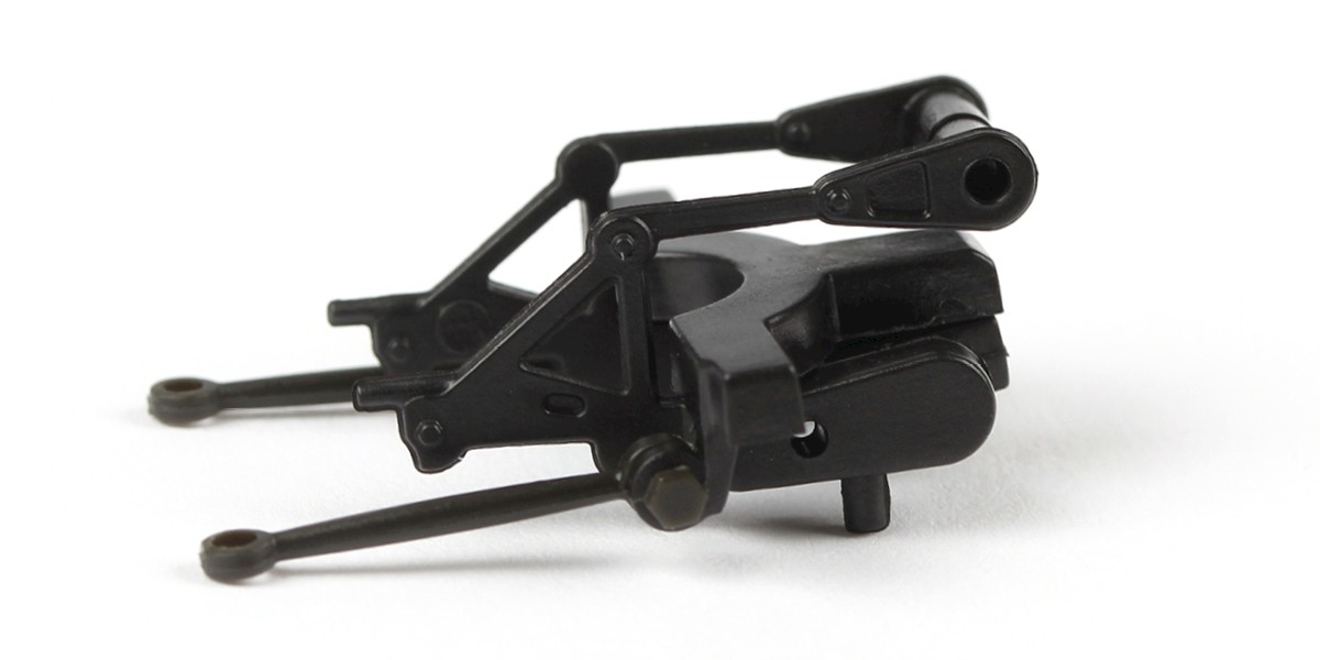
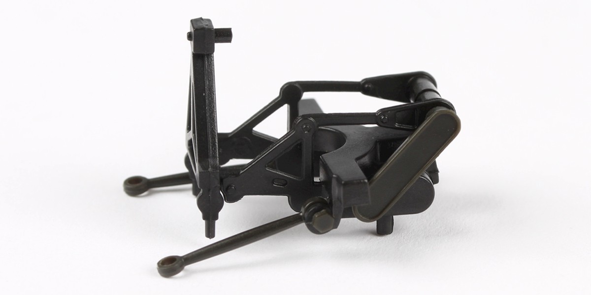
The assembly should look like this.
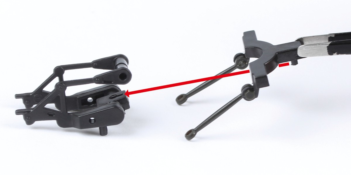
Step 9
Align the two assemblies as shown then fit them together.
Step 10
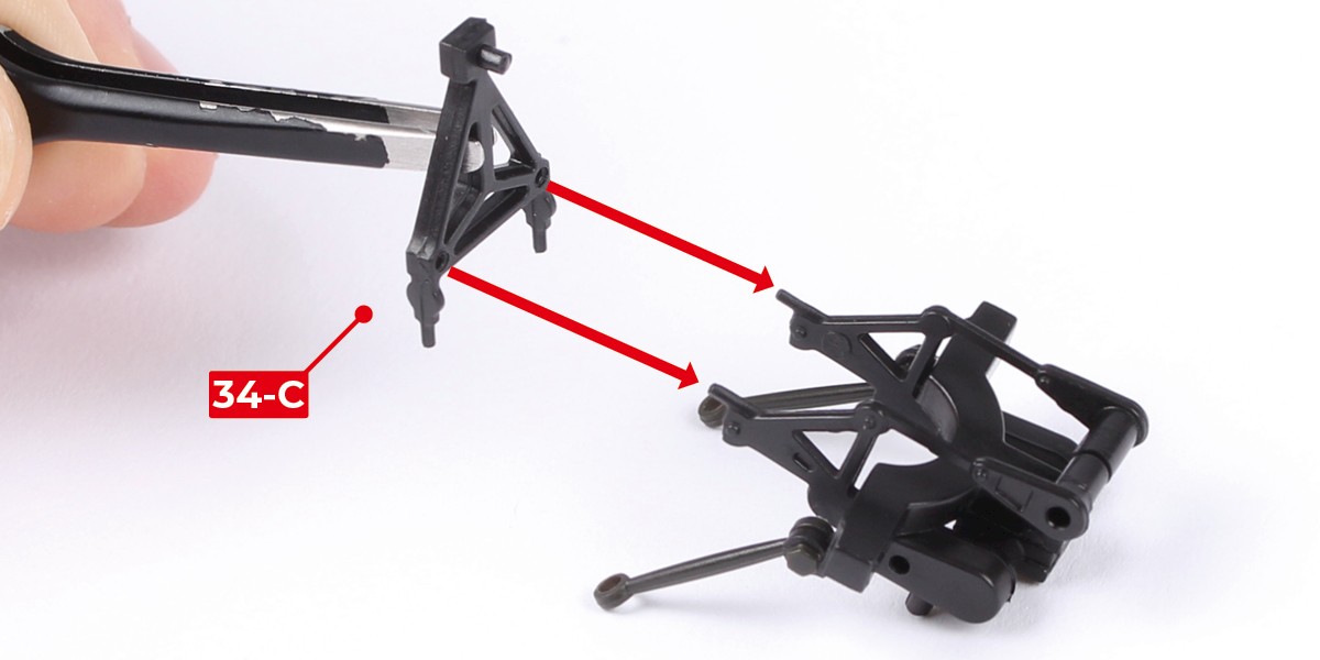
Attach 34-C to the assembly.
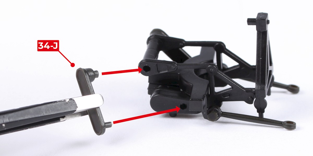
Step 11
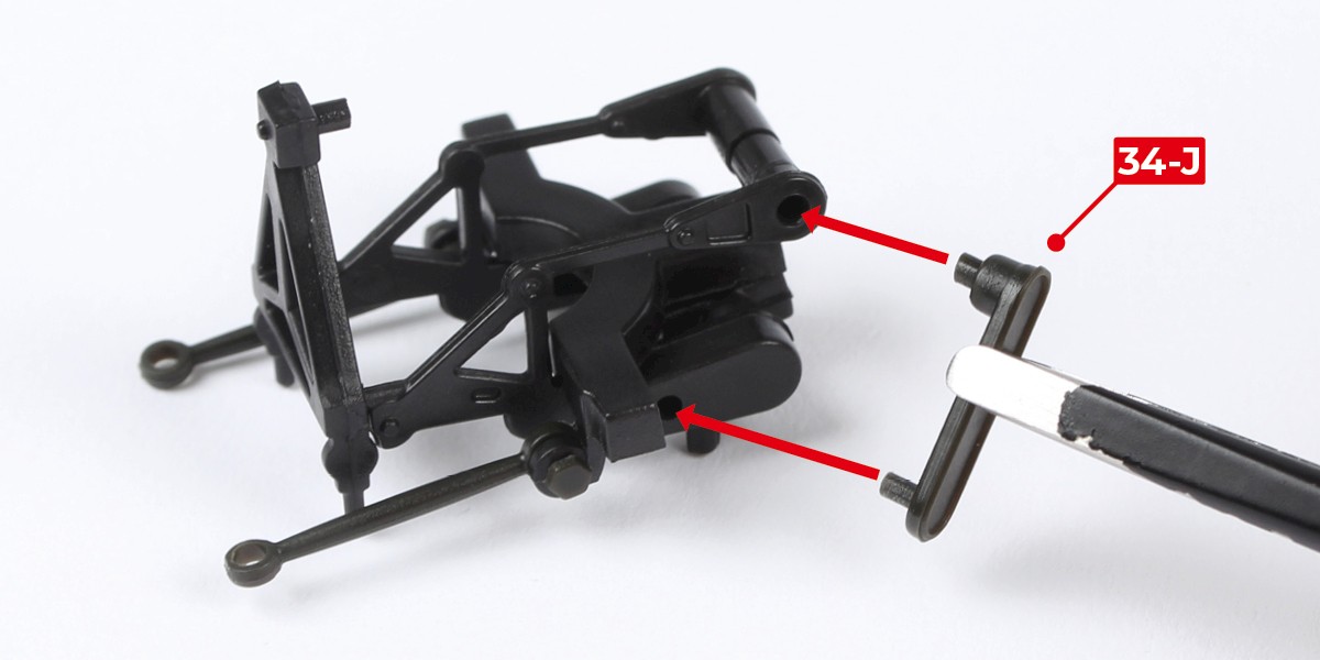
Attach 34-J as shown.
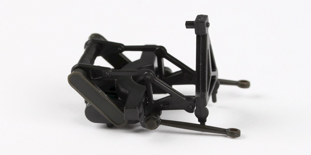
Step 12
Attach the other 34-J to the opposite side.
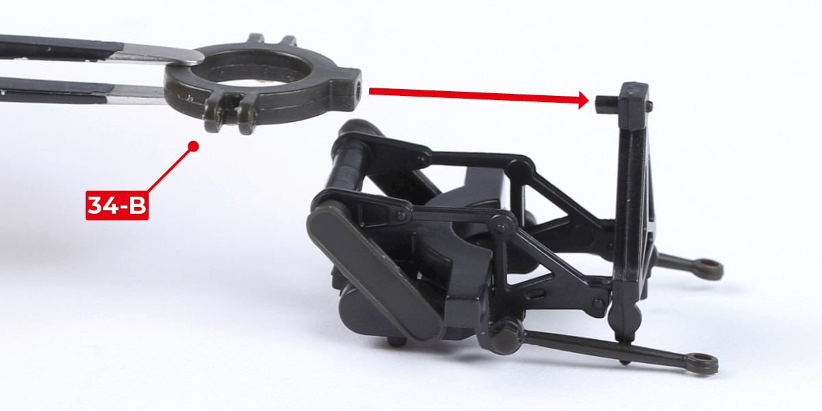
Step 13
Fit 34-B to the assembly.
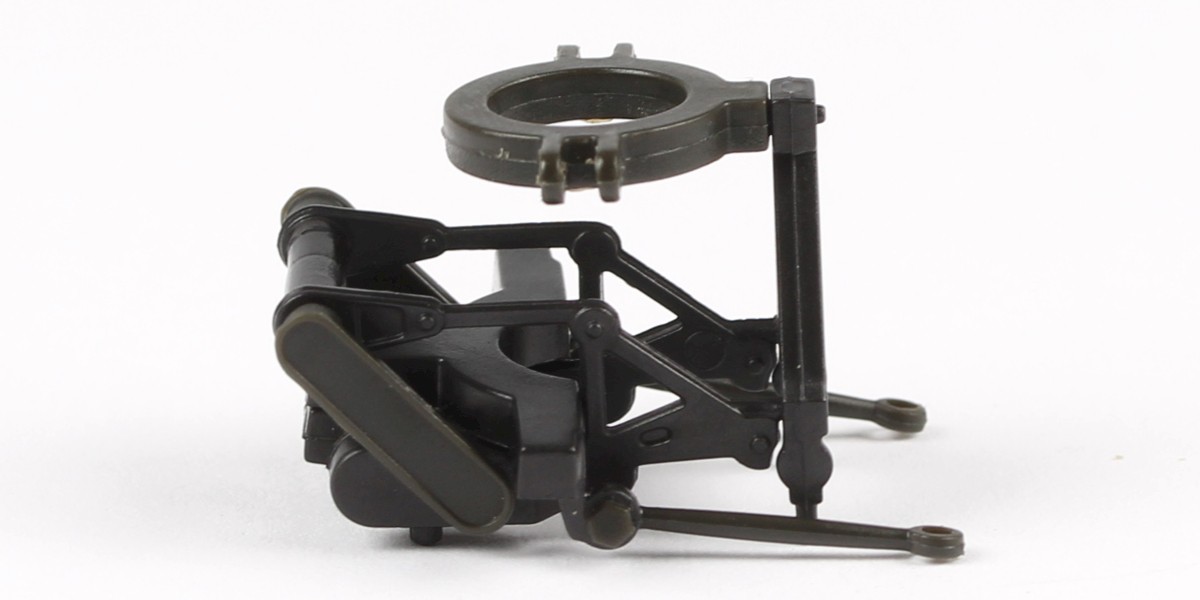
Step 14
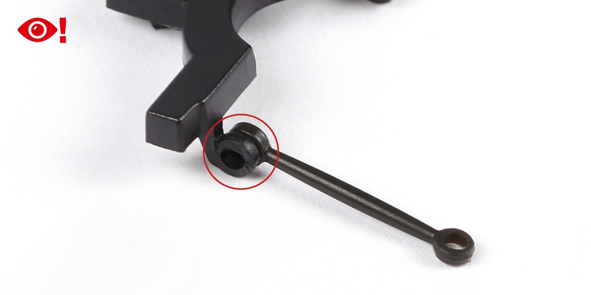
Place the end of 34-H into 34-B.

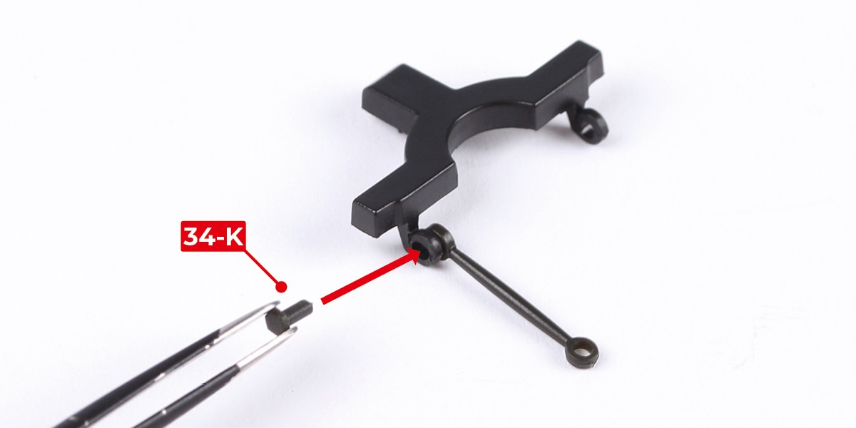
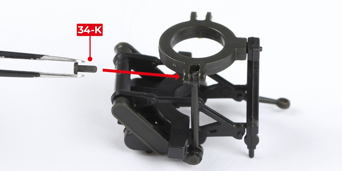
Step 15
Secure the parts using 34-K.
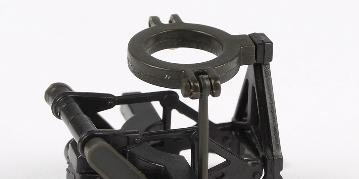
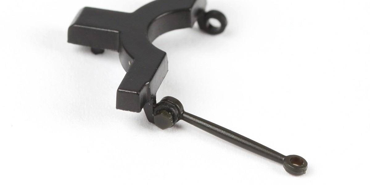
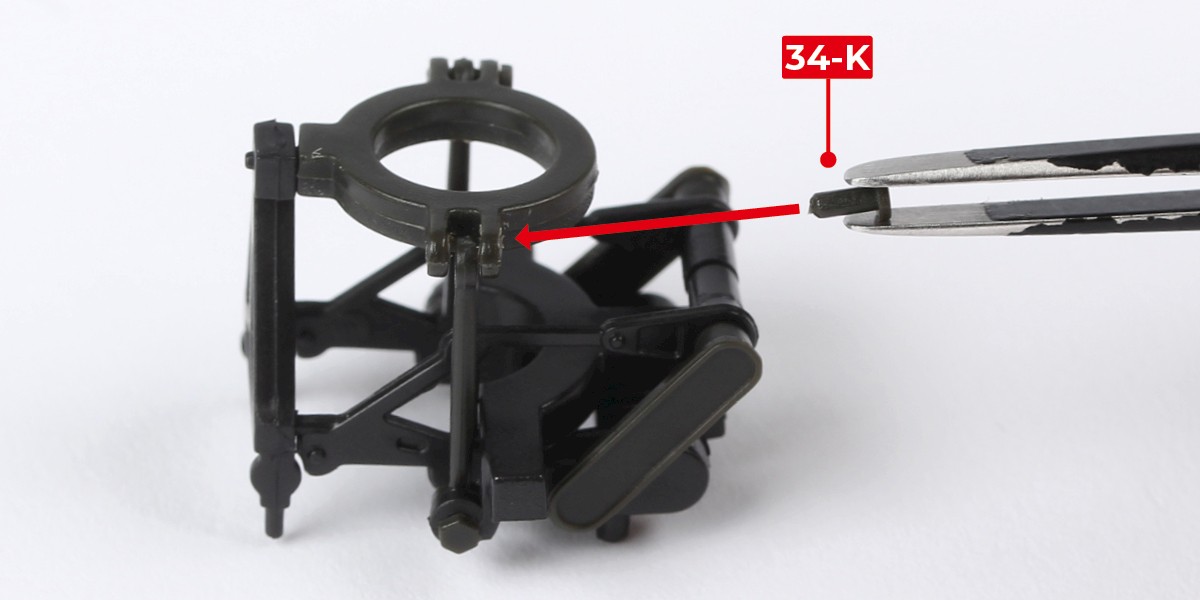
Step 16
Repeat steps 14 and 15 on the other side.

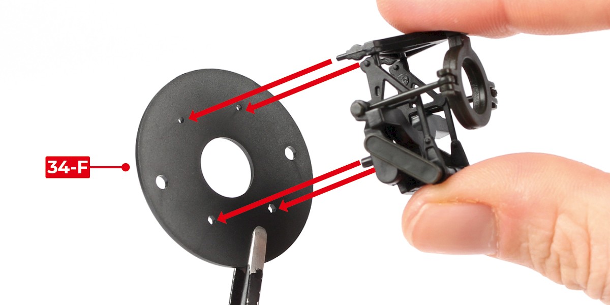
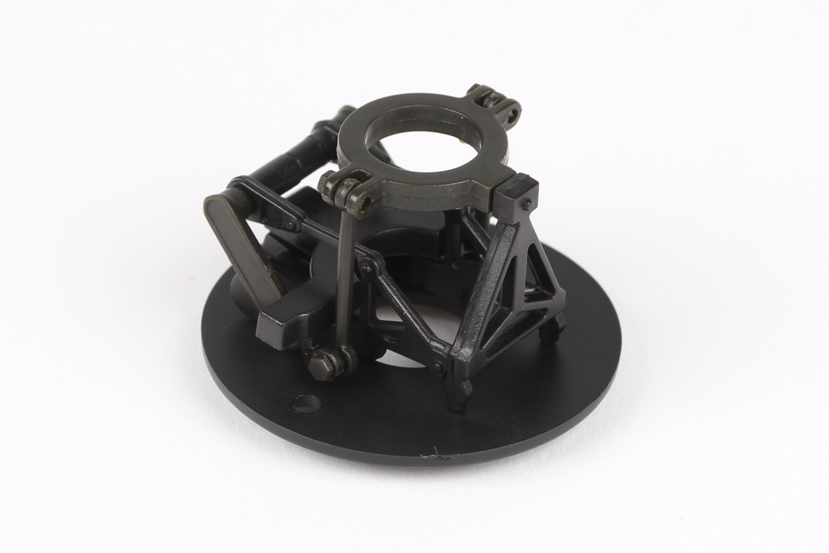
Step 17
Press the assembly onto 34-F.
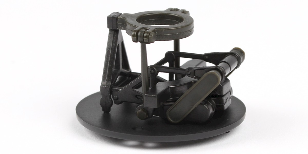
STAGE COMPLETE
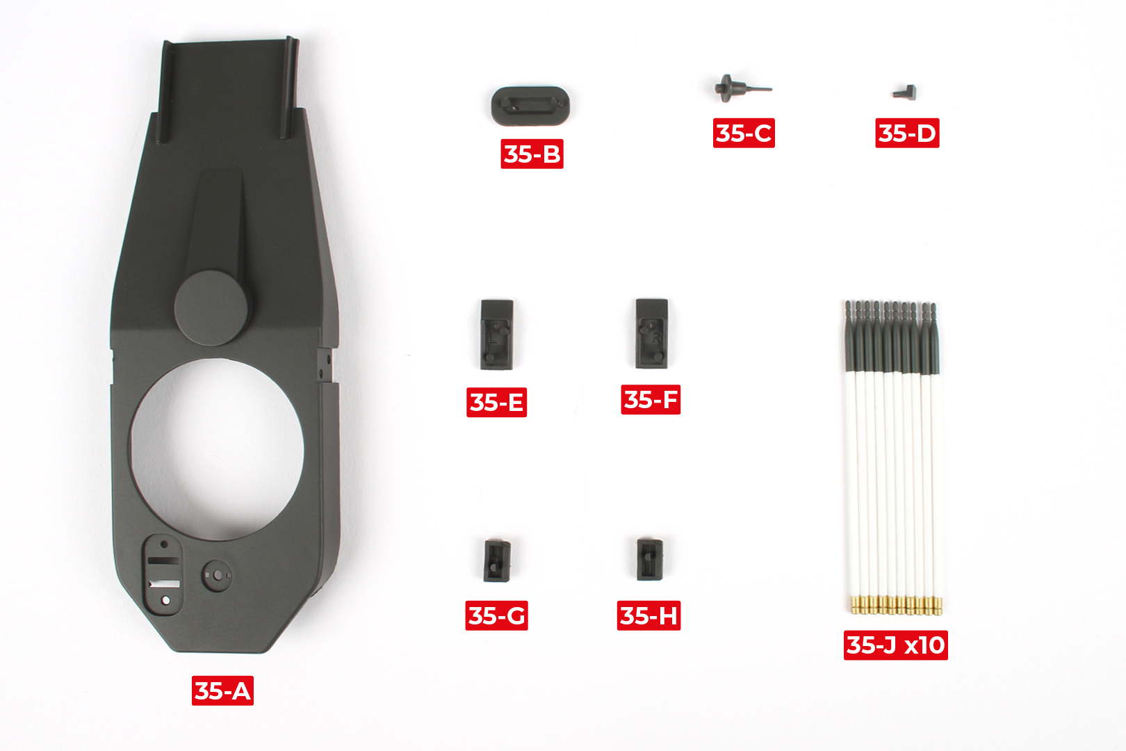
PARTS LIST
| 35-A | 35-D | 35-G |
| 35-B | 35-E | 35-H |
| 35-C | 35-F | 35-J x10 |
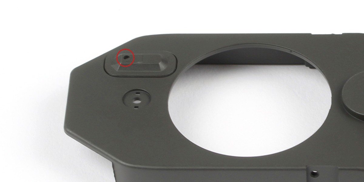
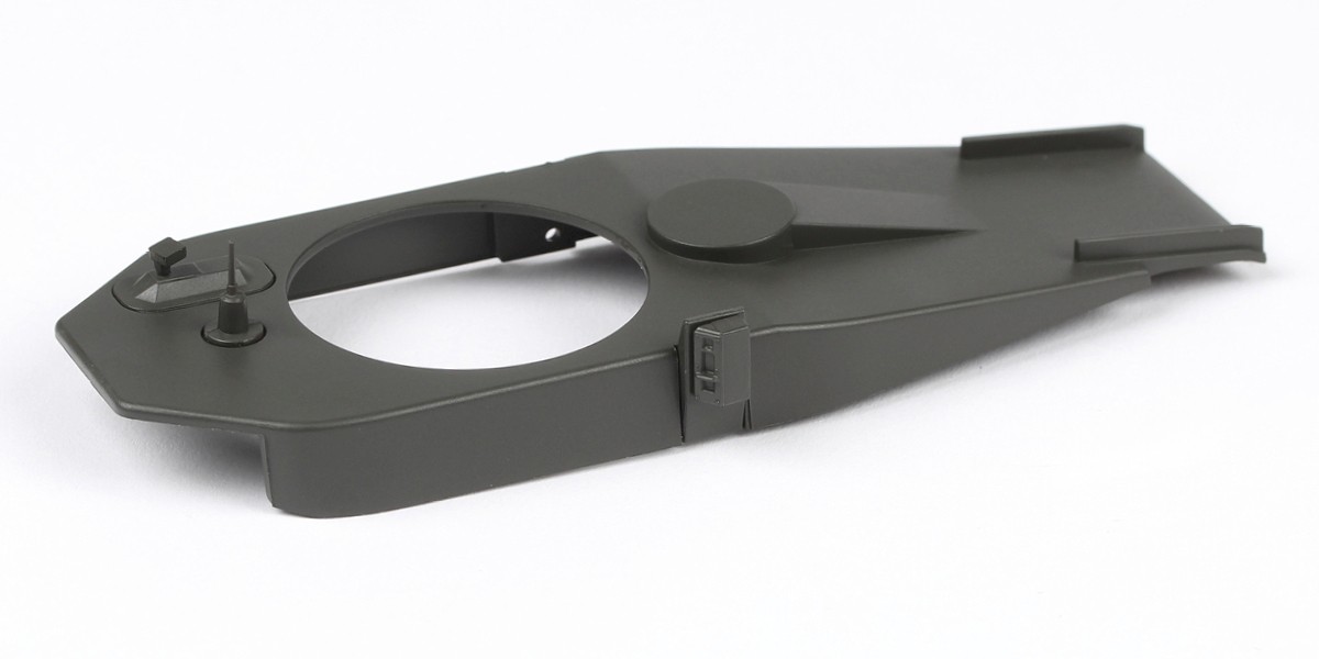
Step 1
Fit 35-B to 35-A.
Make sure 35-B is oriented correctly.
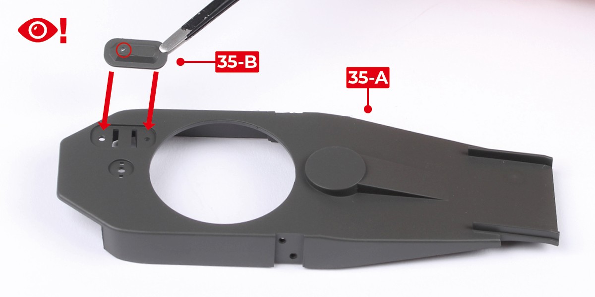
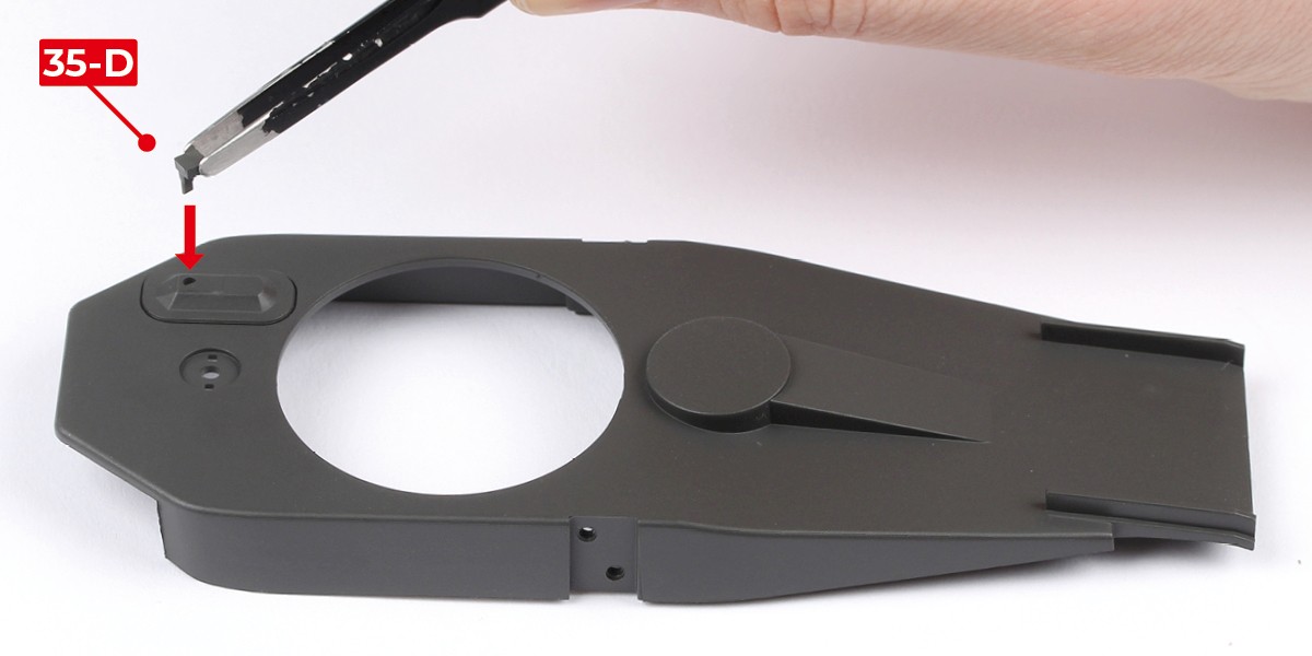
Step 2
Press 35-D onto the assembly.
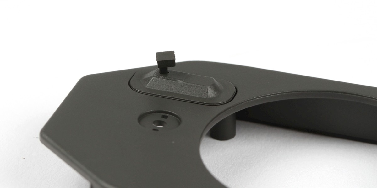
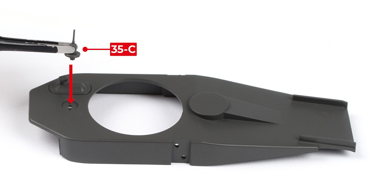
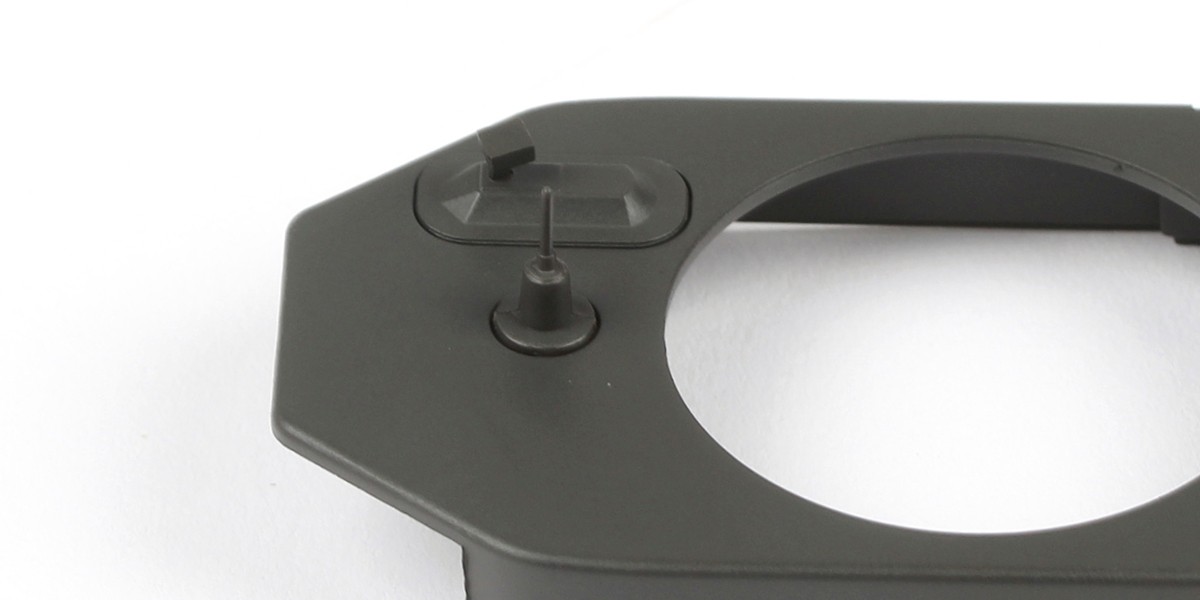
Step 3
Press 35-C onto the assembly.
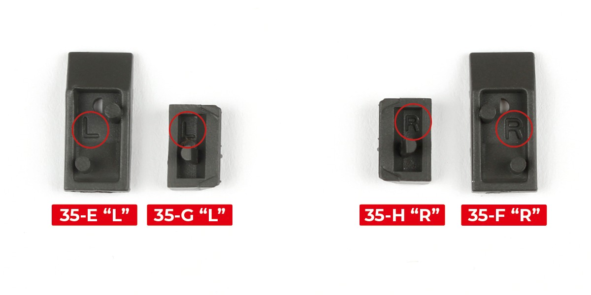
Step 4
Parts 35-E, 35-F, 35-G and 35-H are marked with "L" and "R" (circled).
Group the "L" (left) and "R" (right) parts together.
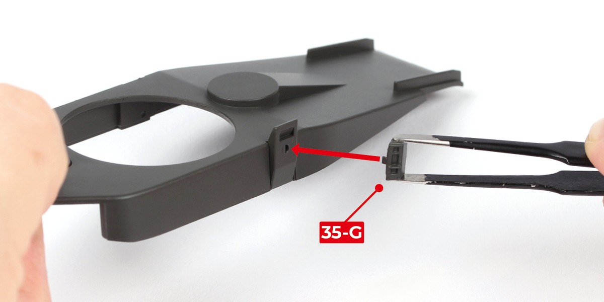
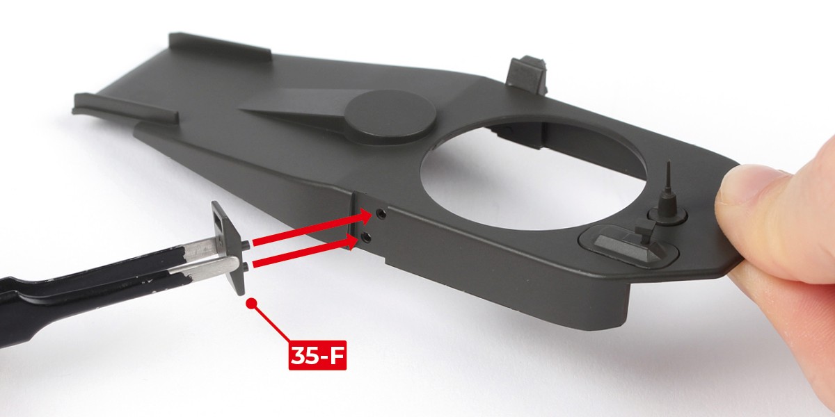
Step 5
Press 35-E onto the left side of the assembly.
Press 35-G onto 35-E.

Step 6
The assembly should look like this.
Step 7
Press 35-F onto the right side of the assembly.
Press 35-H onto 35-F.
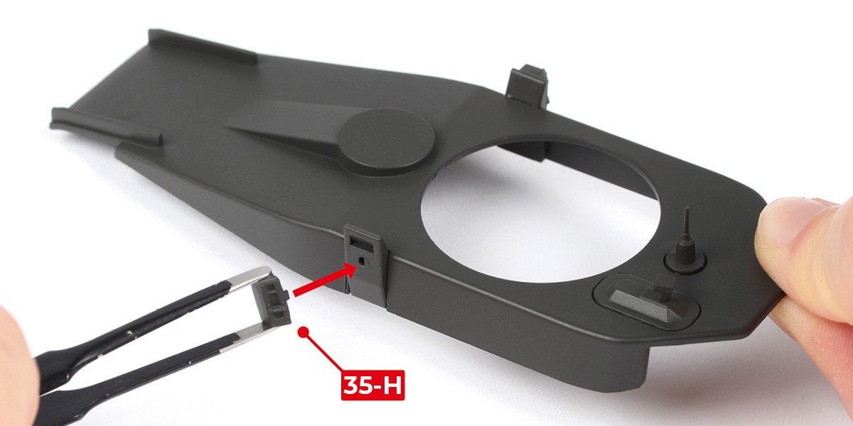
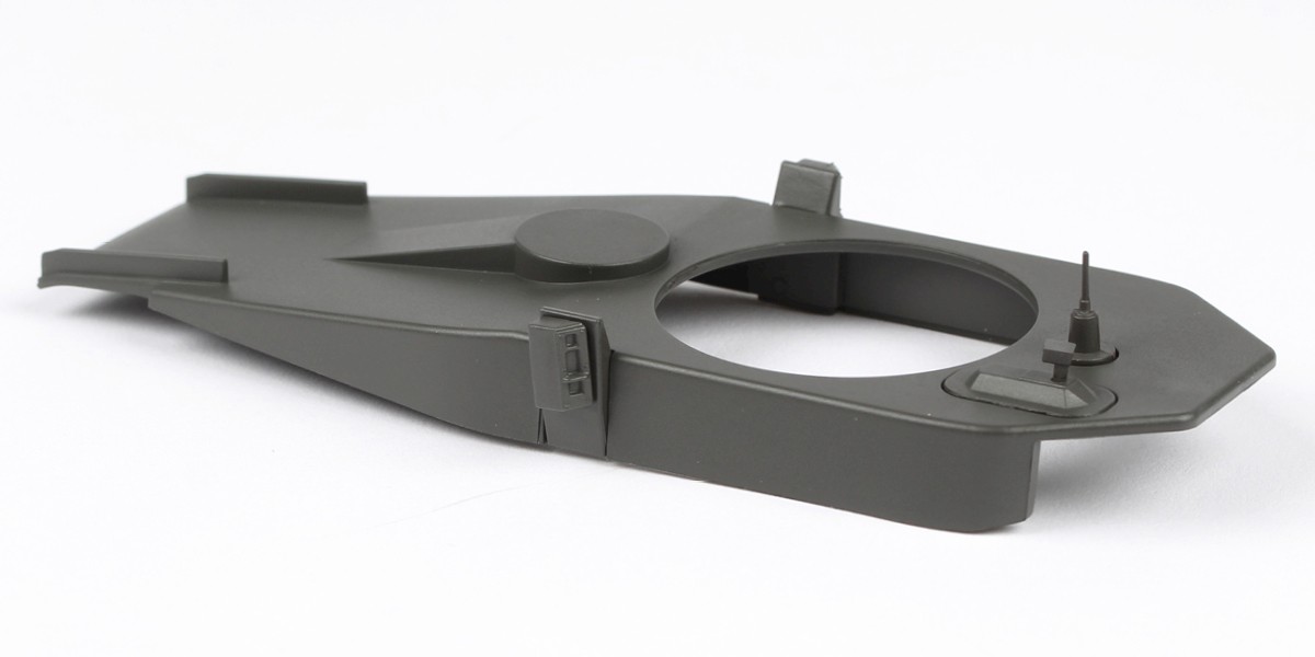
Step 8
The assembly should look like this.
Step 9
Cut the decals outlined in red from 31-J.
Step 10
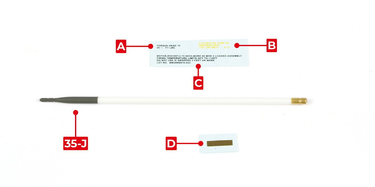
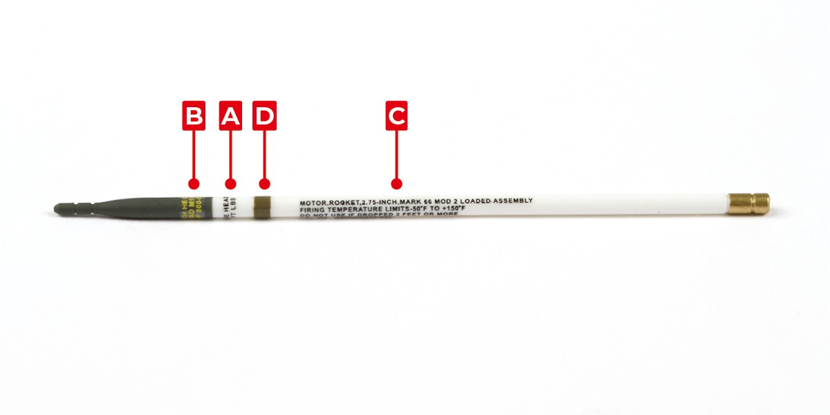
Take 35-J and a set of decals.
Apply decals A, B, C and D to 35-J. Use the rockets from stage 13 as a reference when positioning the decals to help align them.
Step 11
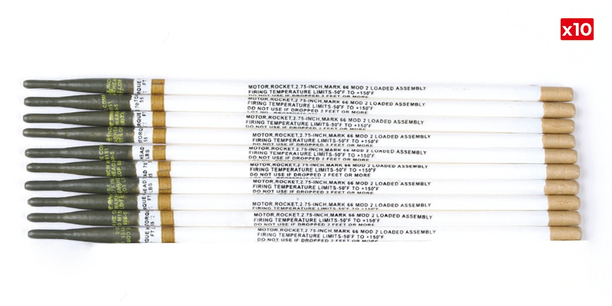
Repeat step 10 to make 10 rockets.
STAGE COMPLETE
PARTS LIST
| 36-A | CM x3 |
| 36-B | FP x3 |
Step 1
Fit 36-B to 36-A.
Screw in place with 2x FP.
Step 2
Thread the cable through the opening.
Press the cable into the recesses. Take care not to damage the connection when bending.
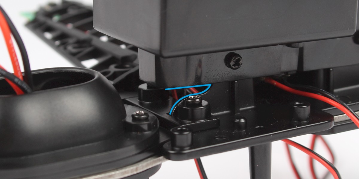
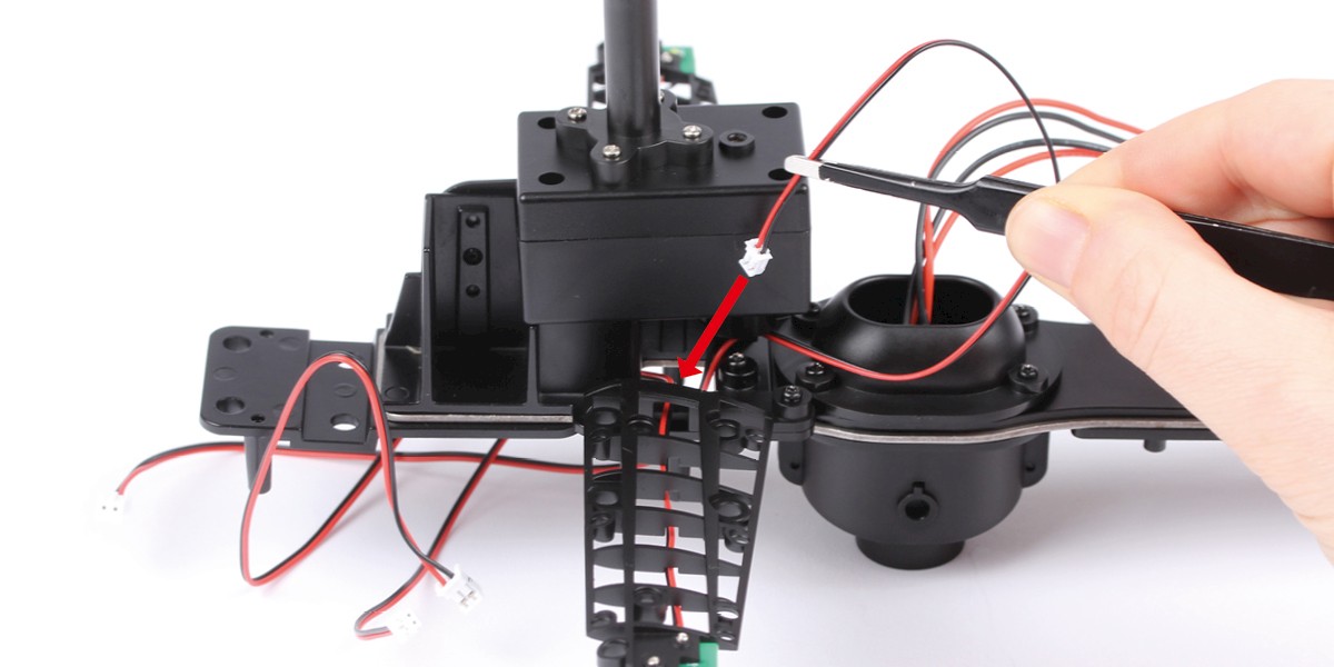
Step 3
Take the main frame assembly and locate the gap underneath the rotor motor box, as indicated by the blue line.
Thread cable M through the gap as shown.
Step 4
Fit the right wing frame to the main frame and secure with 2x CM.
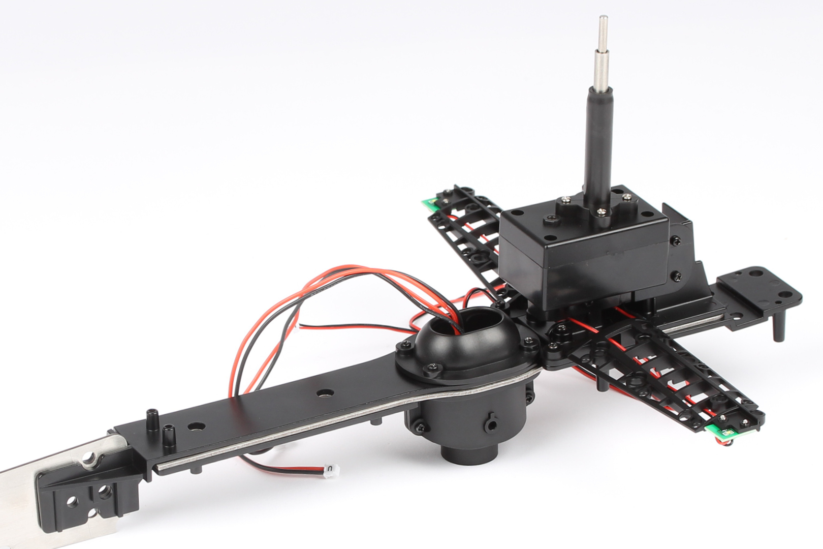
Step 5
Thread cable M through the opening in the main frame.
STAGE COMPLETE
PARTS LIST
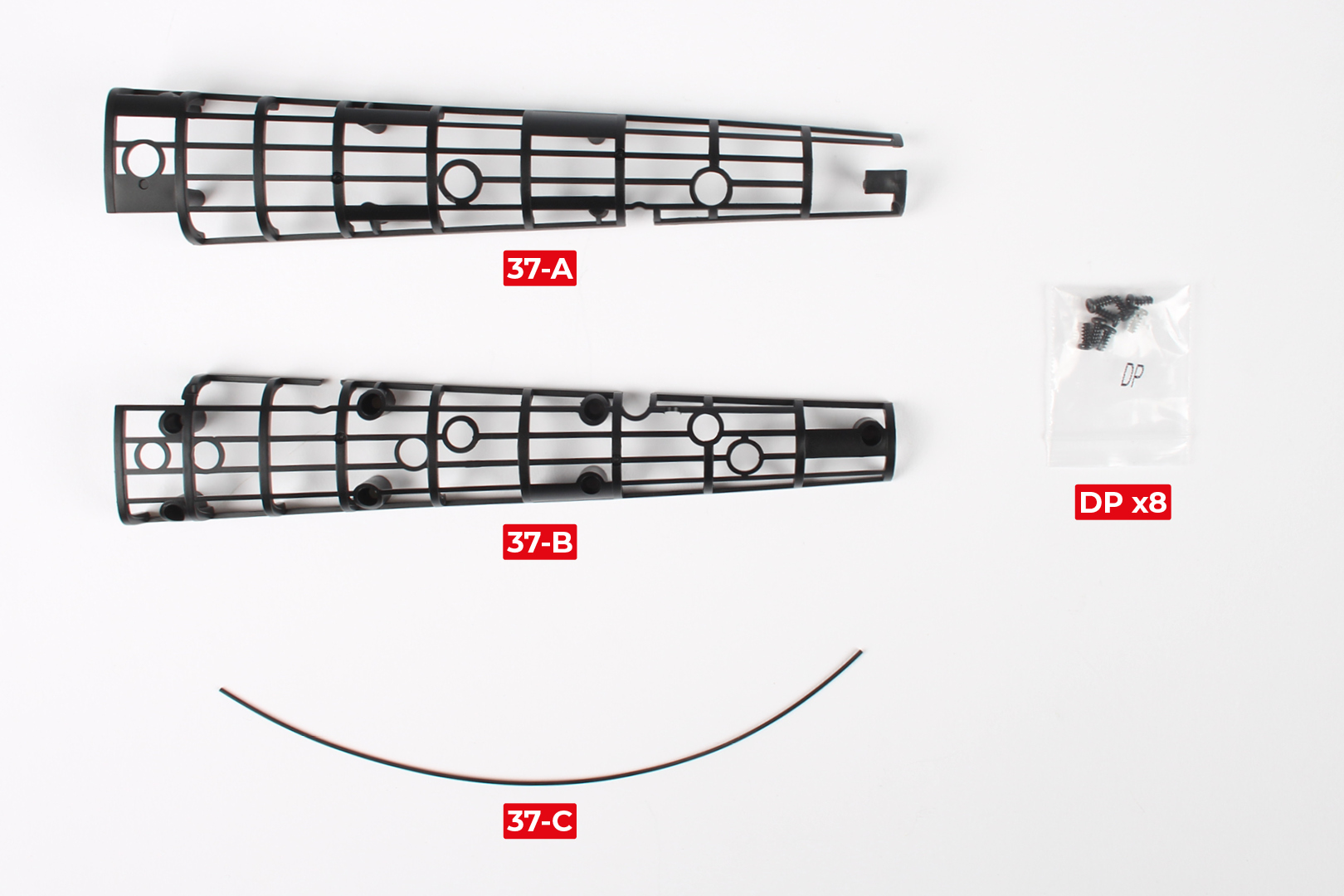
| 37-A | 37-C |
| 37-B* | DP x8* |
* Part 37-B and the DP screws will be used in a later stage. Keep them in a safe place.
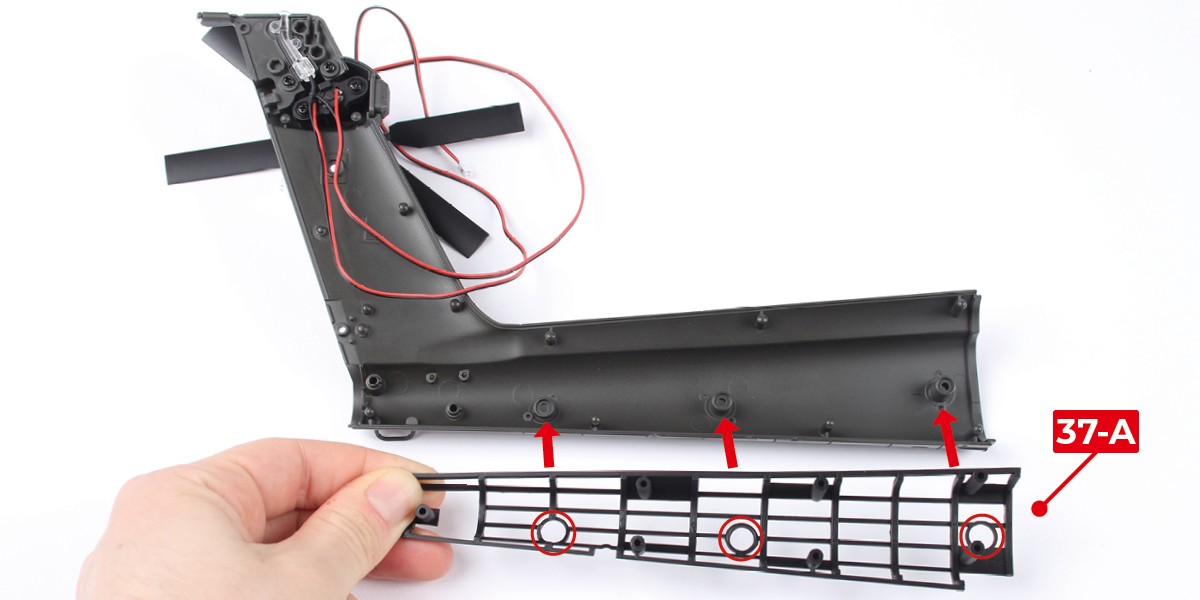
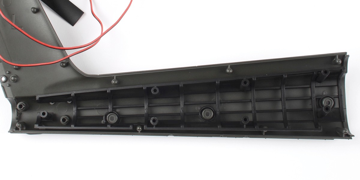
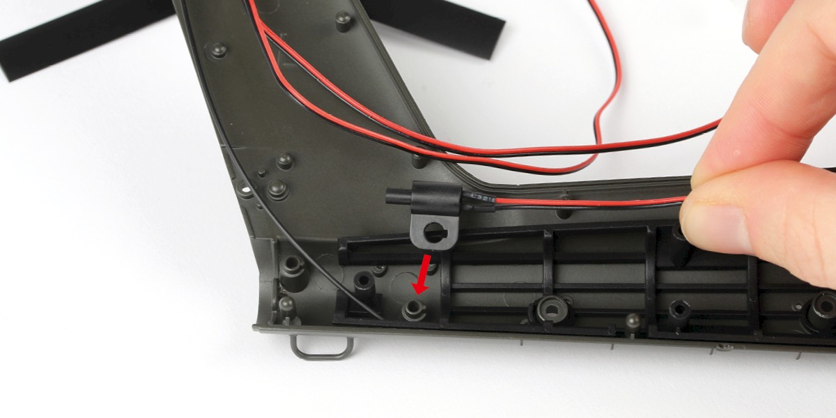
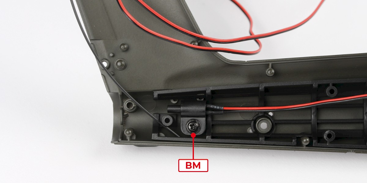
Step 1
Fit 37-A to the left tail fuselage (stage 31).
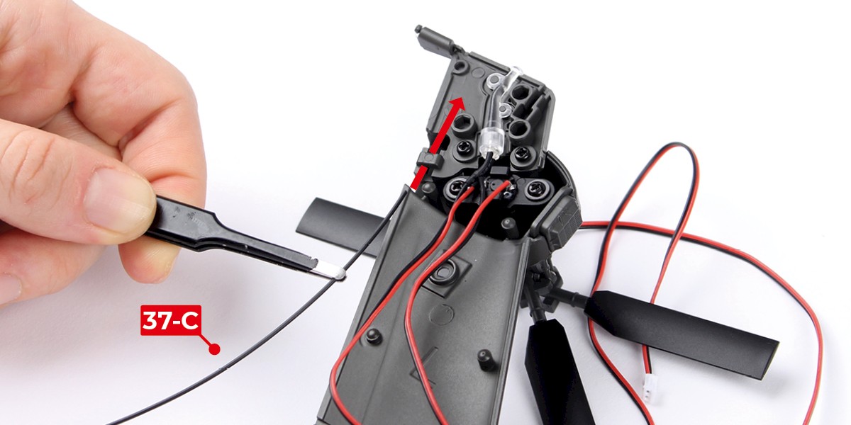
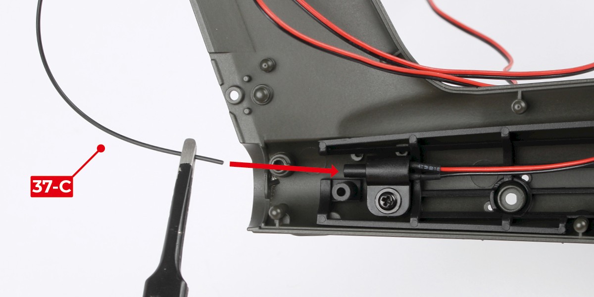
Step 2
Thread 37-C through the bracket then plug it into the rear tail light as shown.

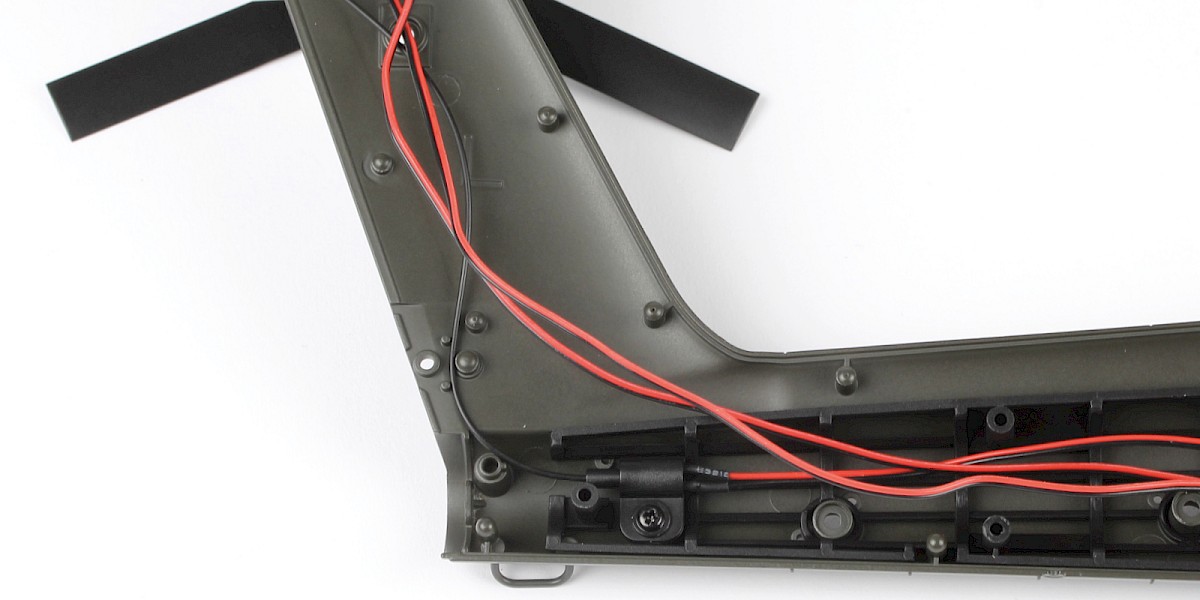
STAGE COMPLETE
PARTS LIST
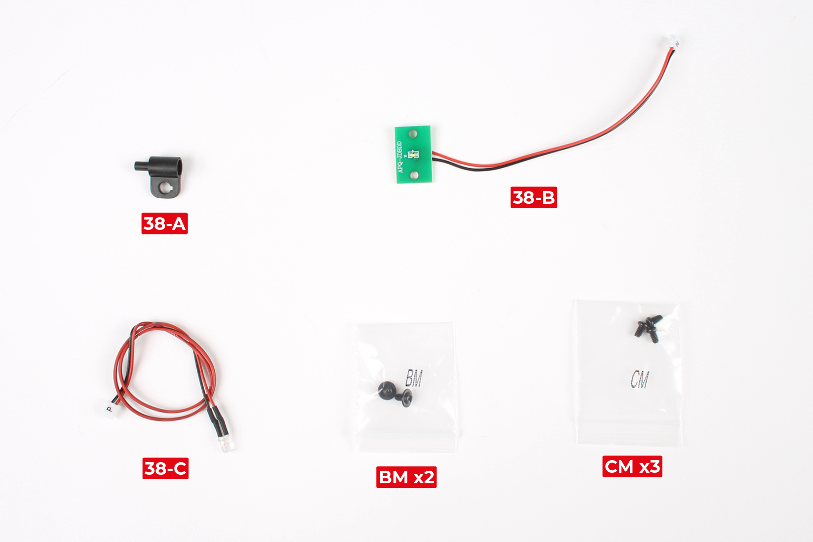
| 38-A | BM x2 |
| 38-B | CM x3 |
| 38-C |
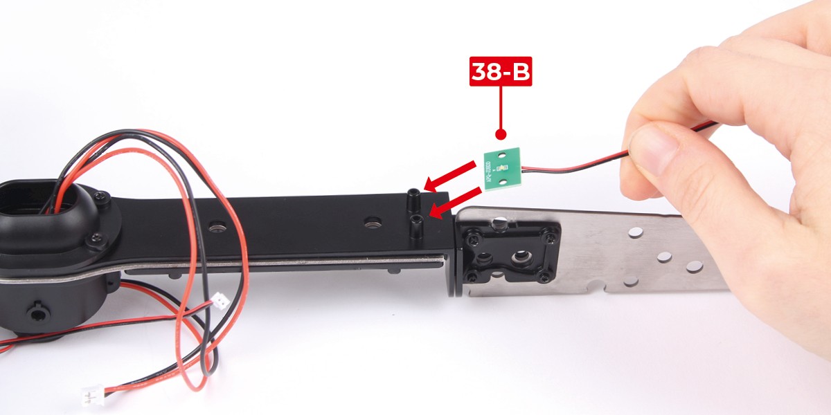
Step 1
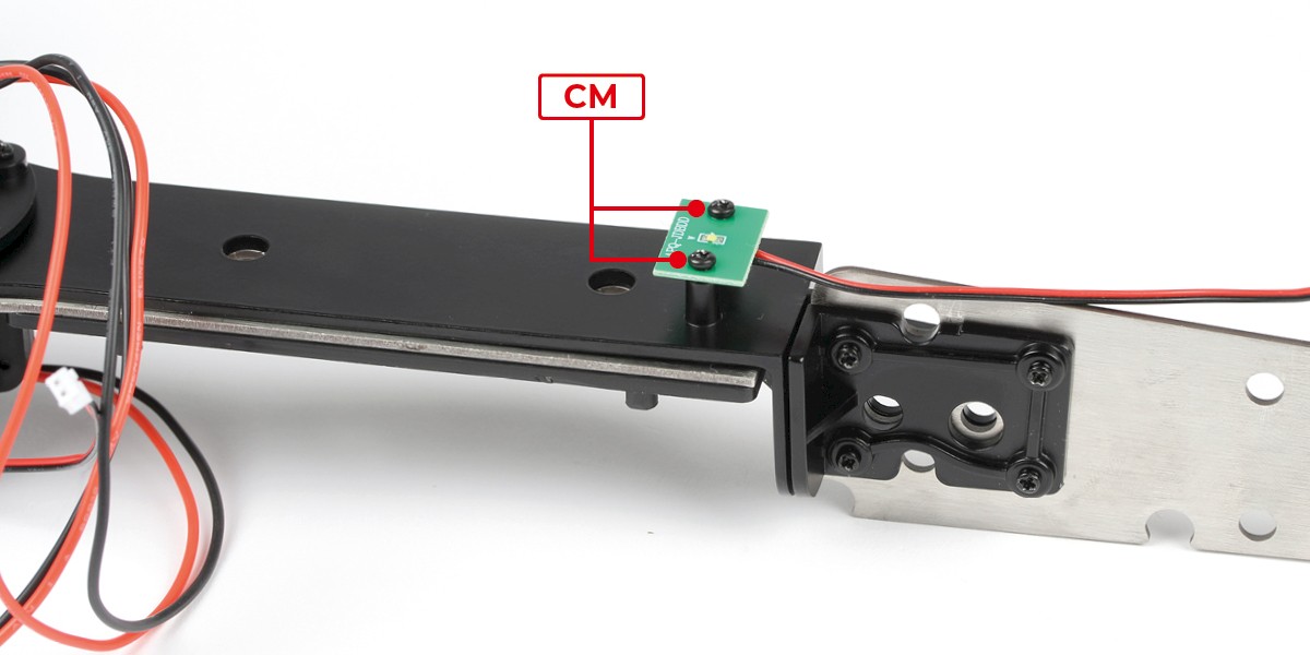
Fit 38-B onto the main frame.
Screw in place with 2x CM.
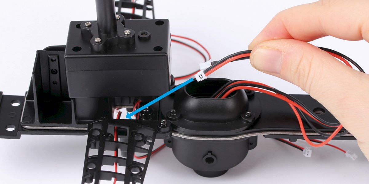
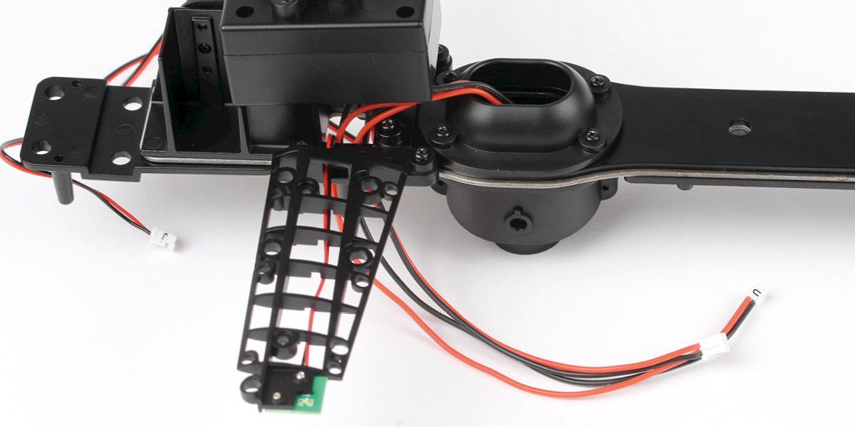
Step 2
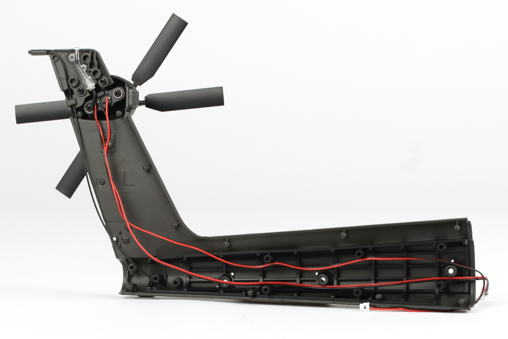
Thread the power cables (marked "T" and "U") through the opening in the main frame as shown.
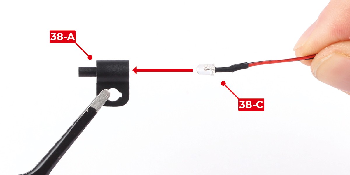
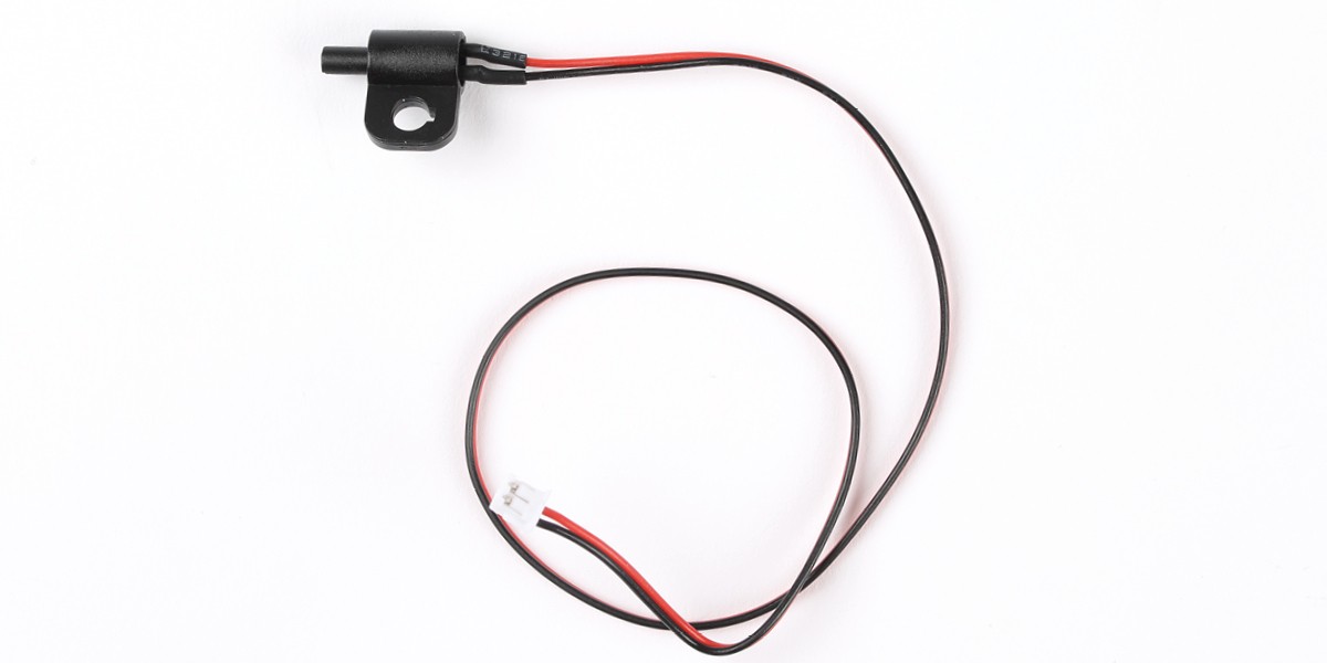
Step 3
Fit 38-C into 38-A.
After fitting, apply a little glue to hold the LED in place.
Step 4
Fit 38-A onto the left tail fuselage (stage 37).
Screw the parts together with 1x BM.
Step 5
Plug 37-C into 38-A.
STAGE COMPLETE

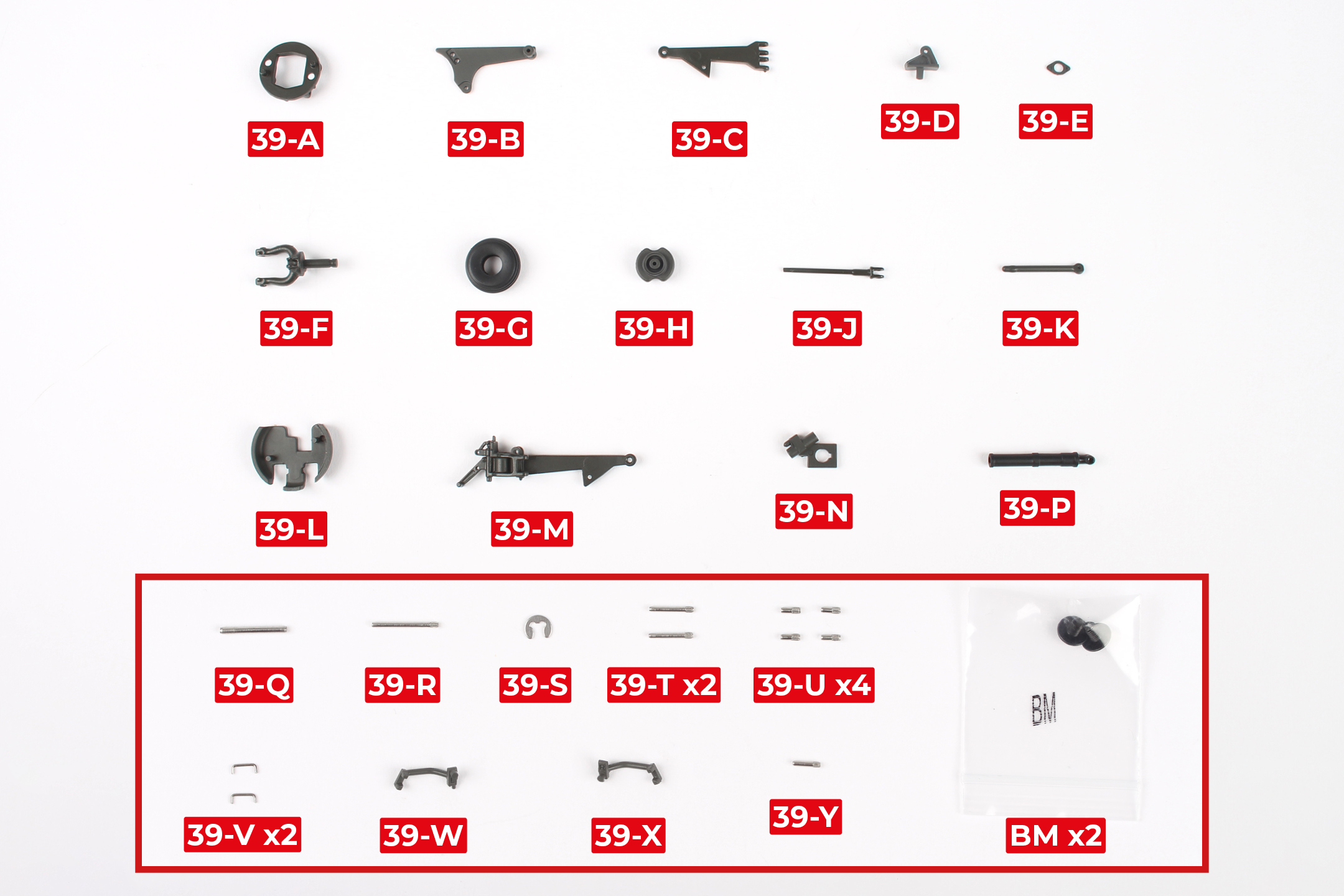
PARTS LIST
| 39-A | 39-H | 39-Q (12mm, smooth) | 39-X |
| 39-B | 39-J | 39-R(12mm) | 39-Y (5.0mm) |
| 39-C | 39-K | 39-S | BM x2 |
| 39-D | 39-L | 39-T (8.0mm) x2 | |
| 39-E | 39-M | 39-U (3.5mm) x4 | |
| 39-F | 39-N | 39-V x2 | |
| 39-G | 39-W |
* The parts in bold have been magnified in the image below. Some of these parts are very small so be careful not to lose them.
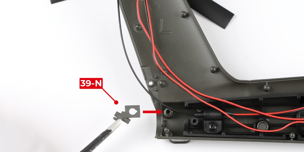
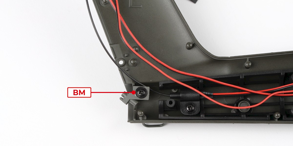
Step 1
Fit 39-N to the left tail fuselage (stage 38).
Screw the parts together using 1x BM.
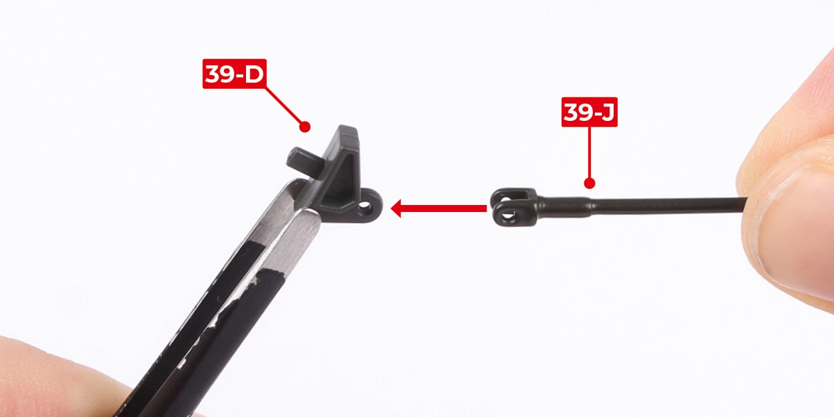
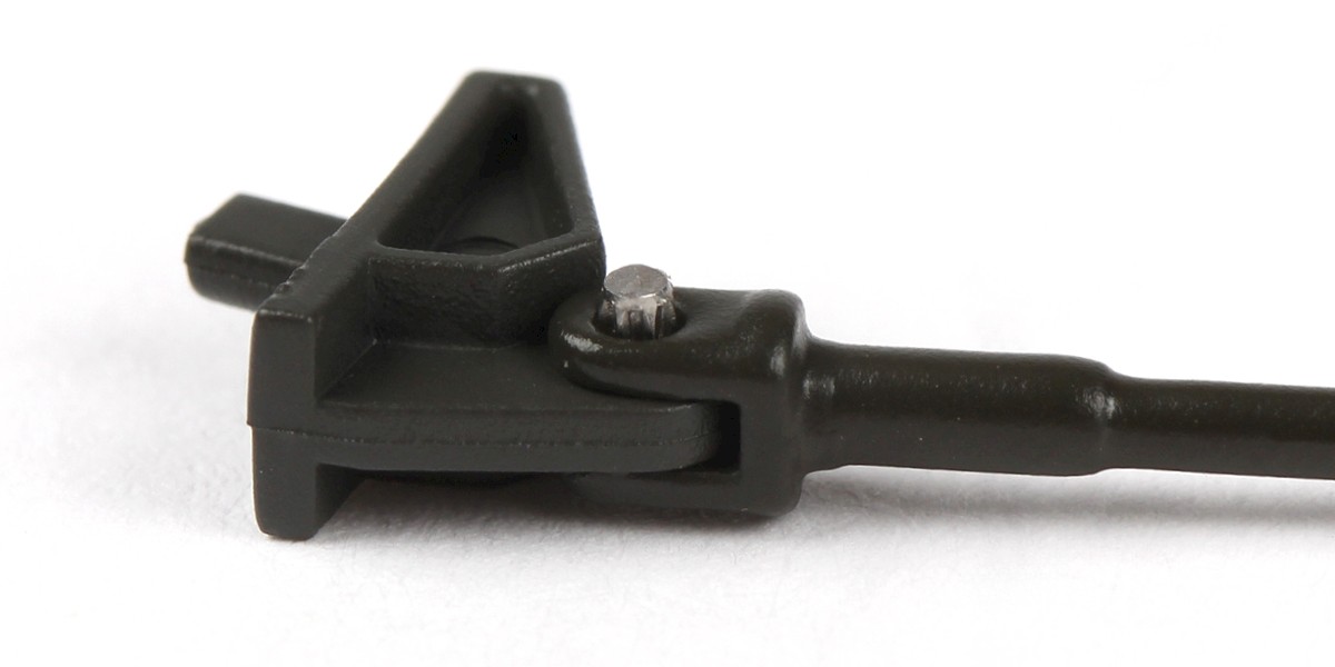
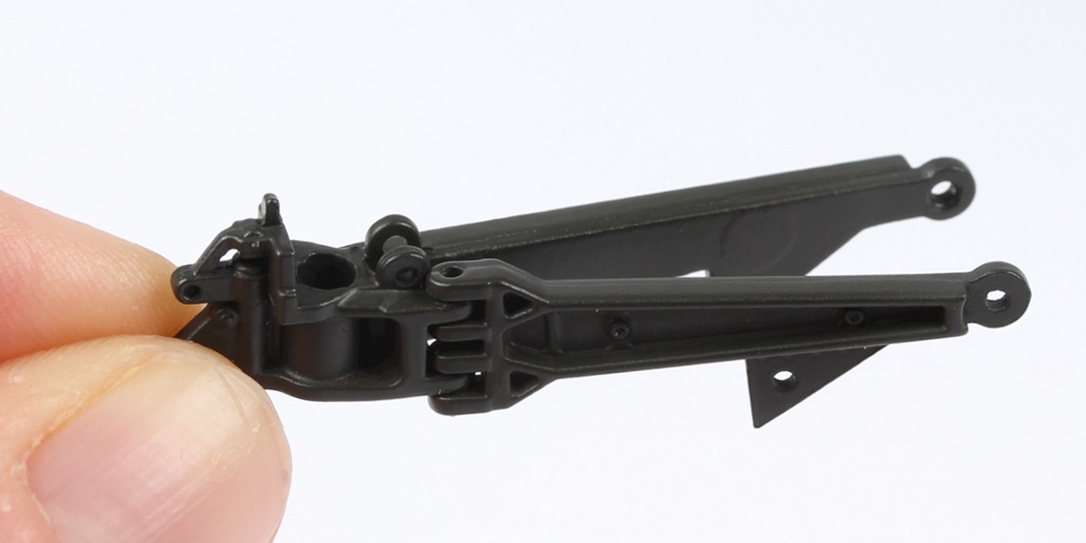
Step 2
Fit 39-J to 39-D.
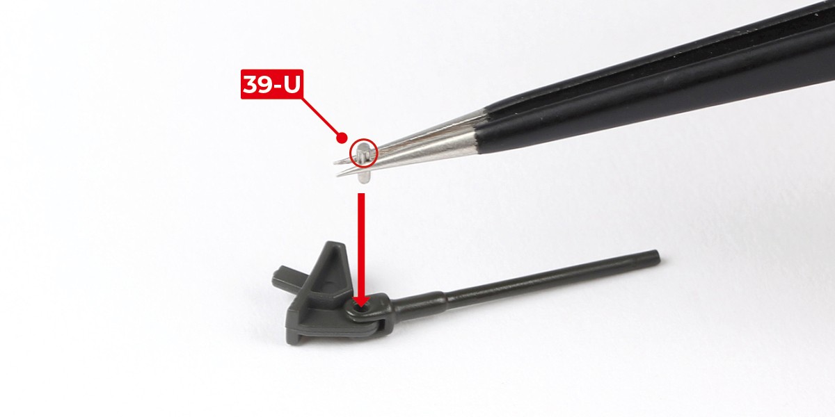
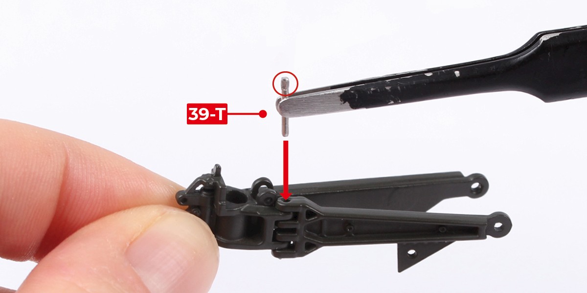
Step 3
Secure the parts together by pushing 39-U into the joint. Insert the smooth end first.
Step 4
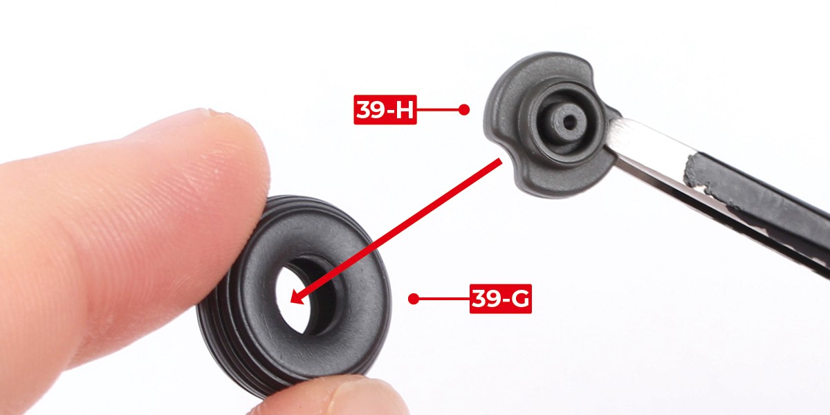
You will now build the tail wheel.
Place 39-G into hot water for 1–2 mins to soften it.
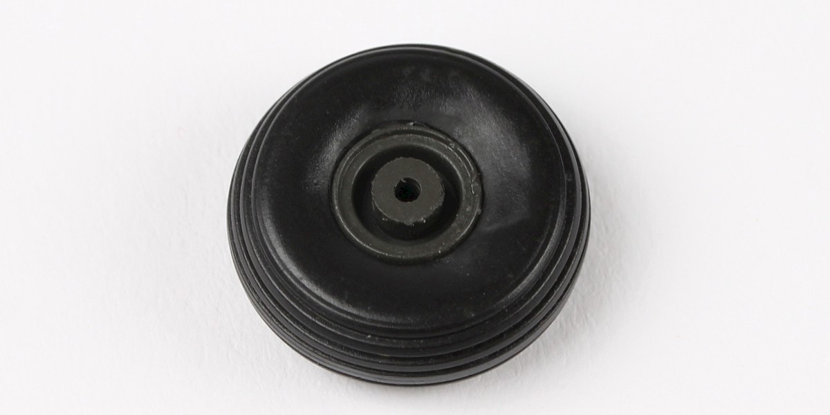
Carefully remove 39-G from the water then fit it to 39-H.
Step 5
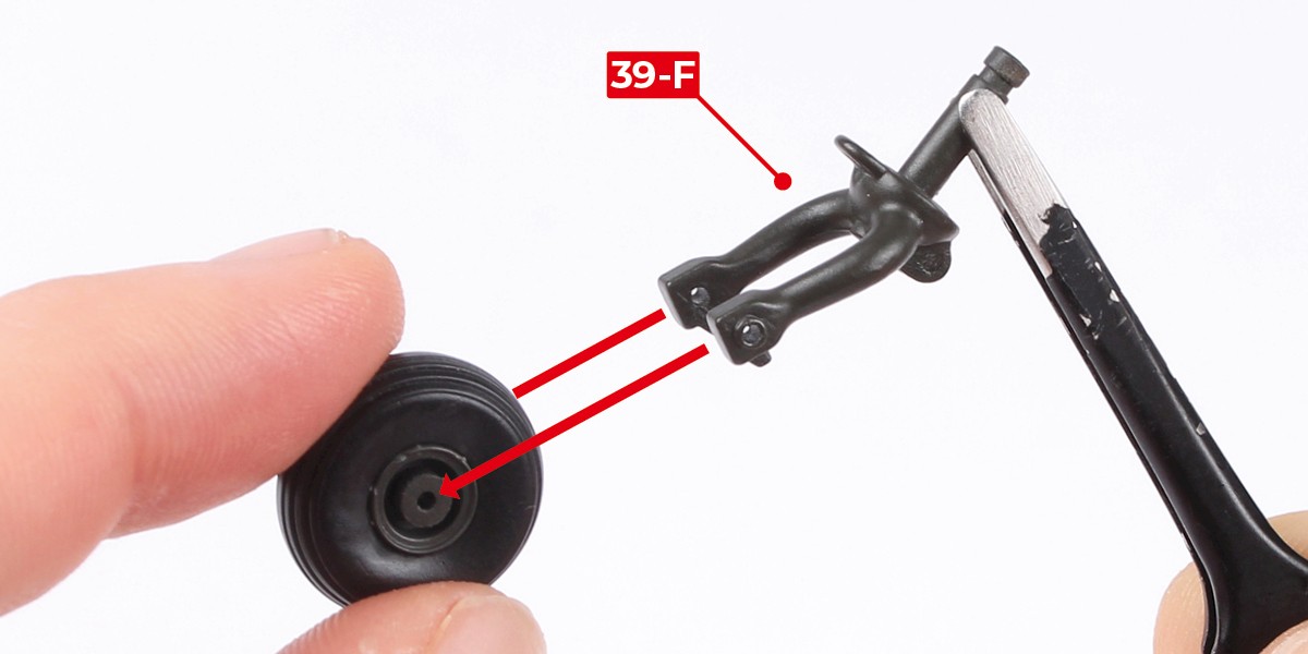
Fit 39-F to the wheel.
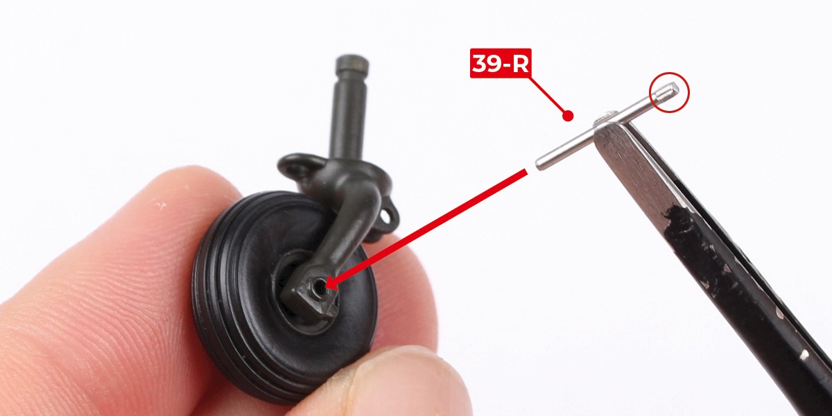
Step 6
Fix in place with 39-R, fitting the smooth end first.
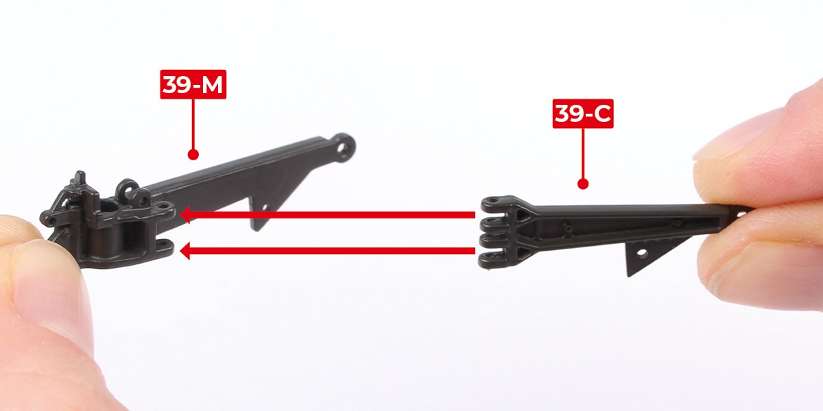
Step 7
Fit 39-C to 39-M.
Step 8
Fix in place with 39-T, fitting the smooth end first.
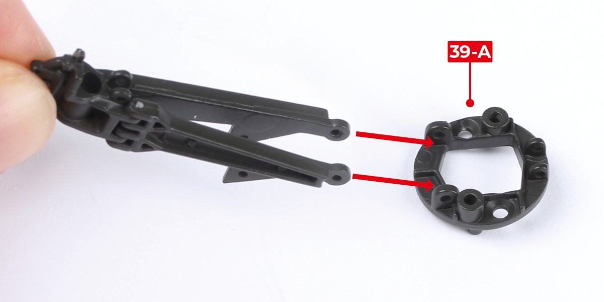
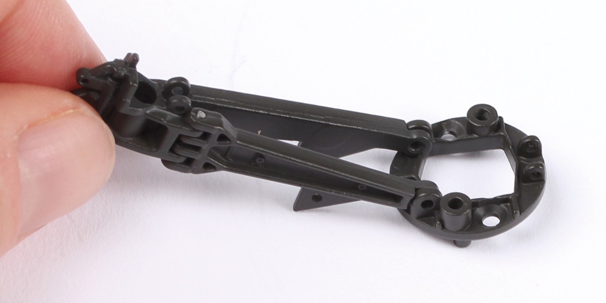
Step 9
Fit the assembly onto 39-A as shown.
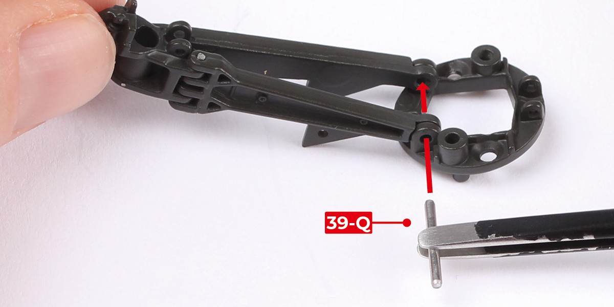
Step 10
Fix in place with 39-Q.
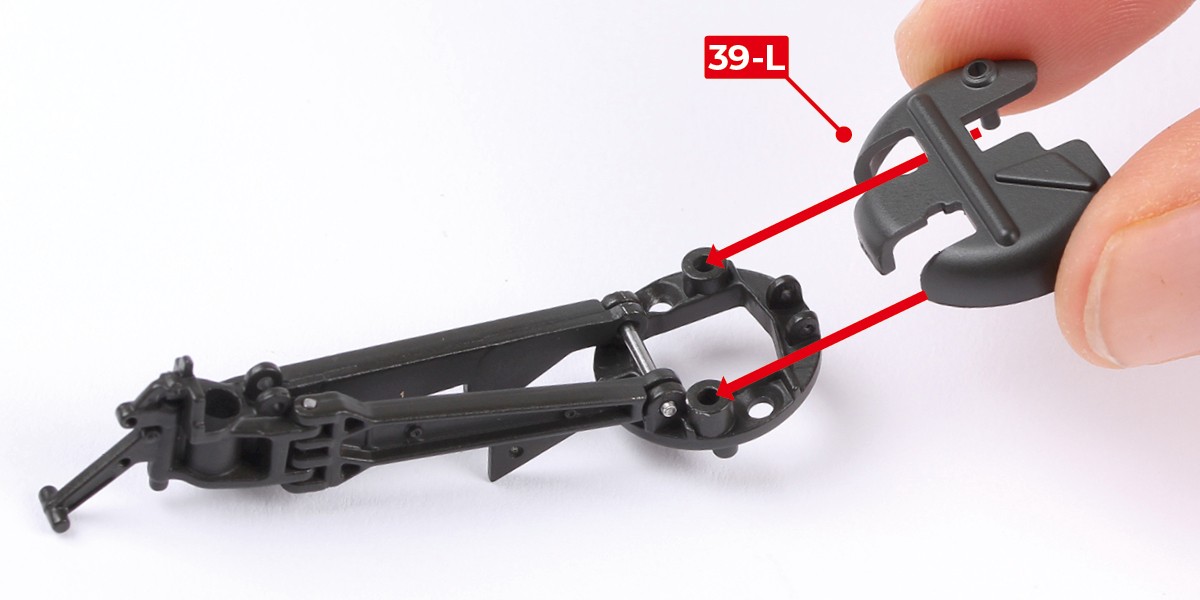
Step 11
This image shows where 39-L fits onto the assembly.
However, we recommend not fitting the part at this stage as you will need to access the screw holes in order to attach the assembly onto your model. Instructions will be provided in a later pack on how to do this.
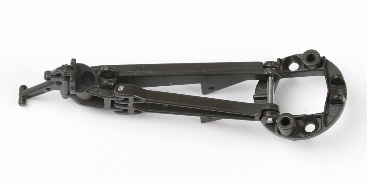
Step 12
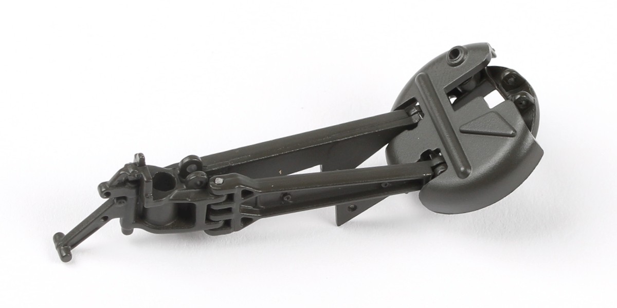
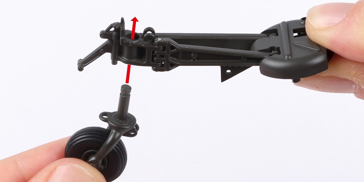
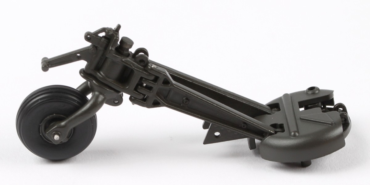
Insert the wheel assembly as shown.
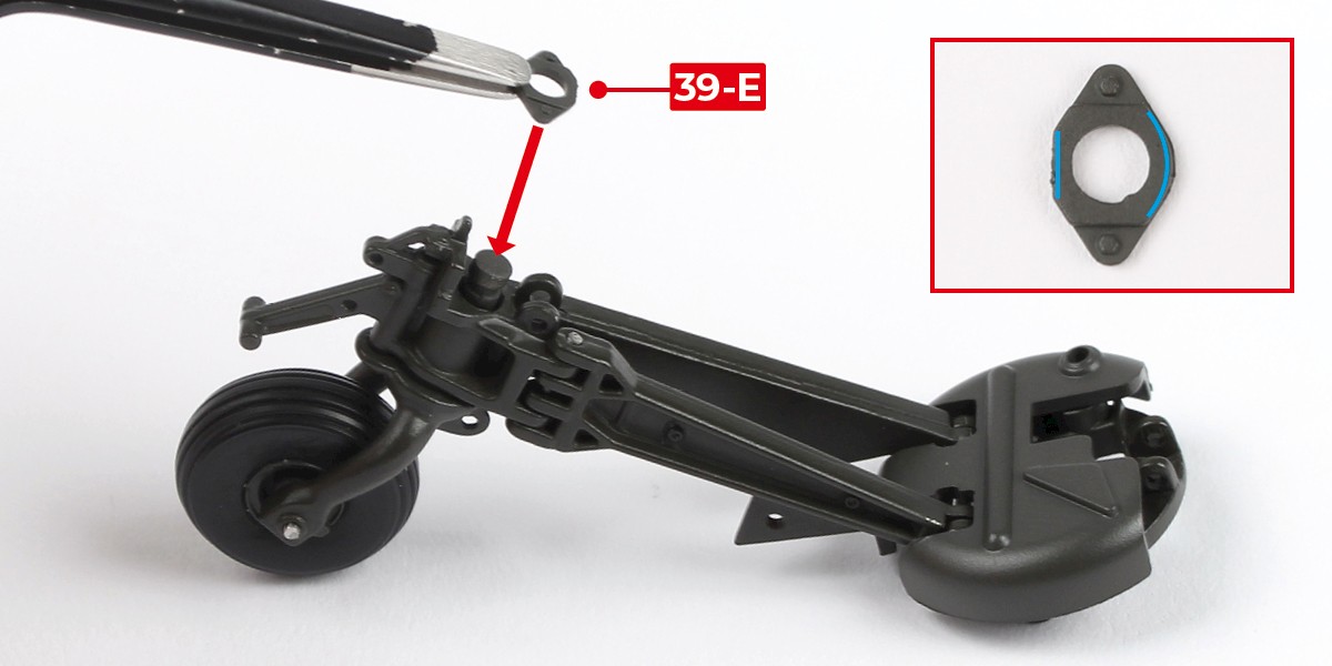
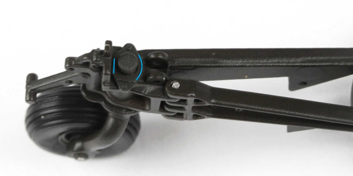
Step 13
Take part 39-E. One side has a flat edge, the other is curved (shown by the blue lines). Fit 39-E in the orientation shown.
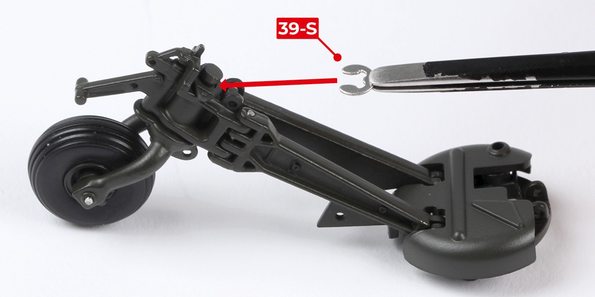
Step 14
Secure the parts by fitting 39-S as shown.
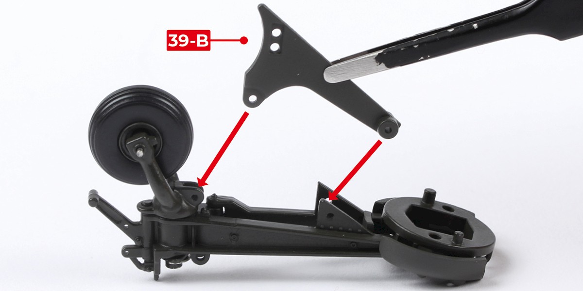
Step 15
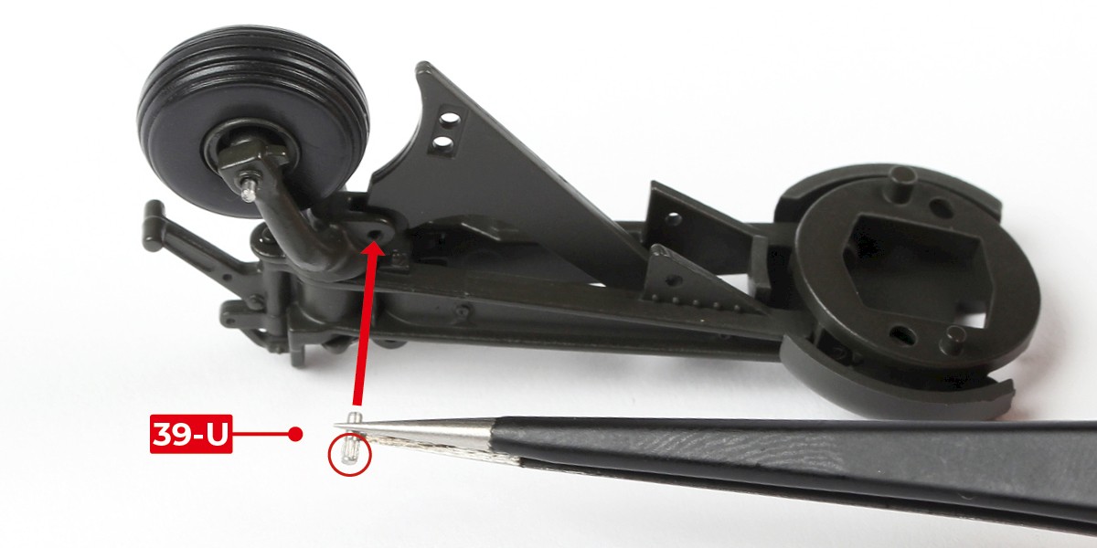
Turn the assembly over and attach 39-B as shown.
Fix in place with 39-U, fitting the smooth end first.
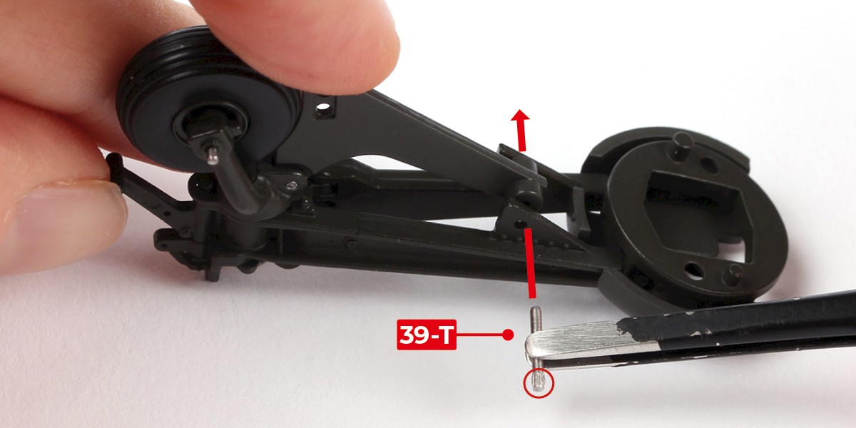
Step 16
Continue to fix the parts using 39-T, fitting the smooth end first.
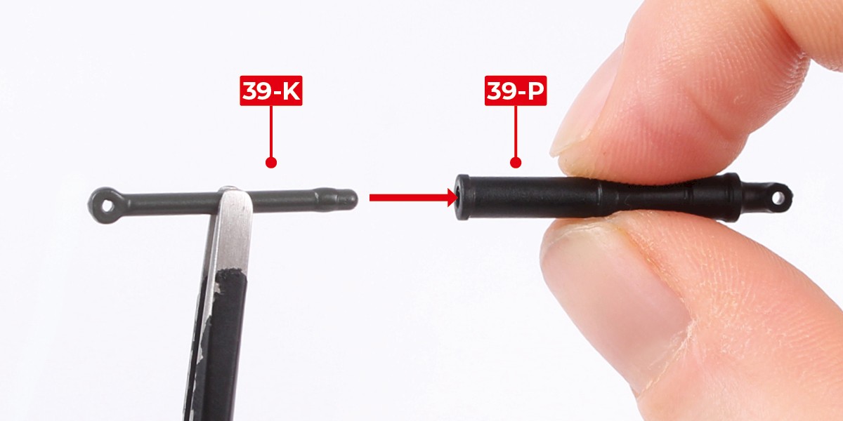
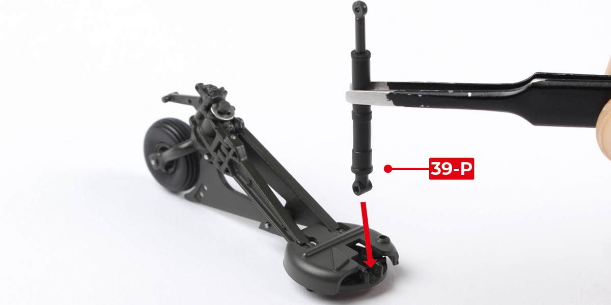
Step 17
Press 39-K into 39-P.
You may need to remove some excess paint from 39-K.
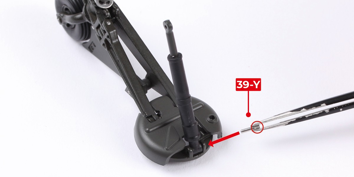
Step 18
Fit 39-P to the assembly.
Fix in place with 39-Y, fitting the smooth end first.
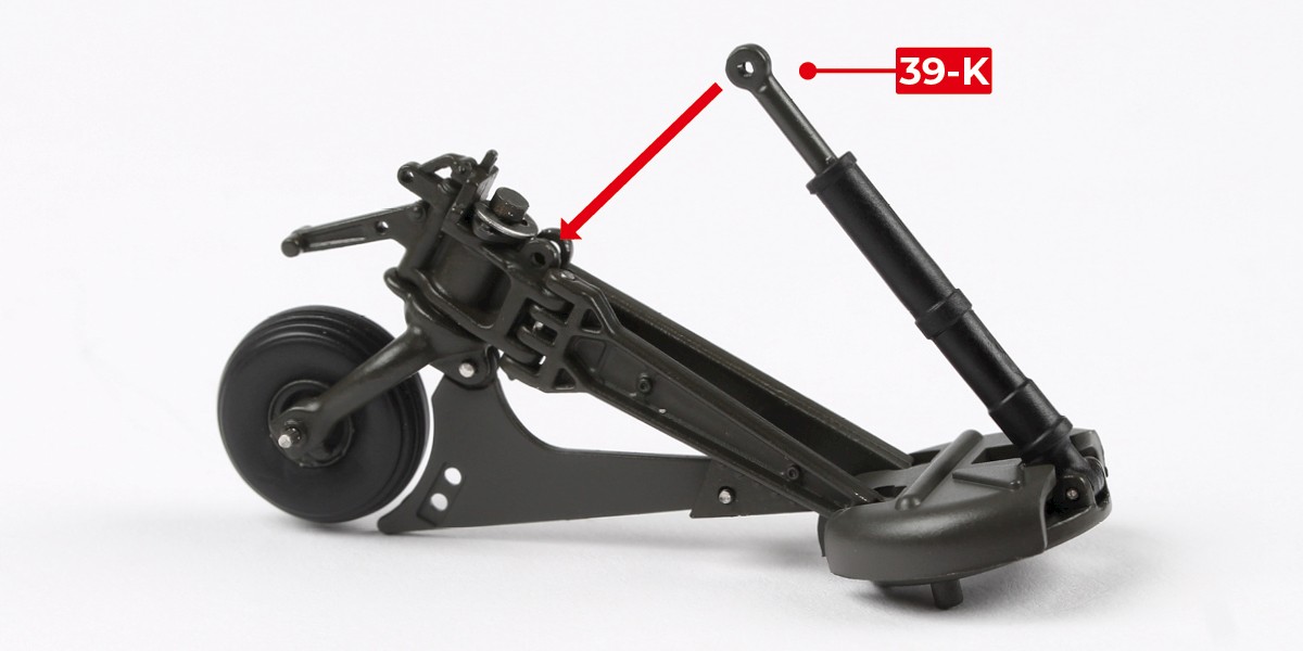
Step 19
Position 39-K on the assembly as shown.
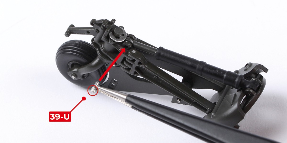
Step 20
Fix in place with 39-U, fitting the smooth end first.
Step 21
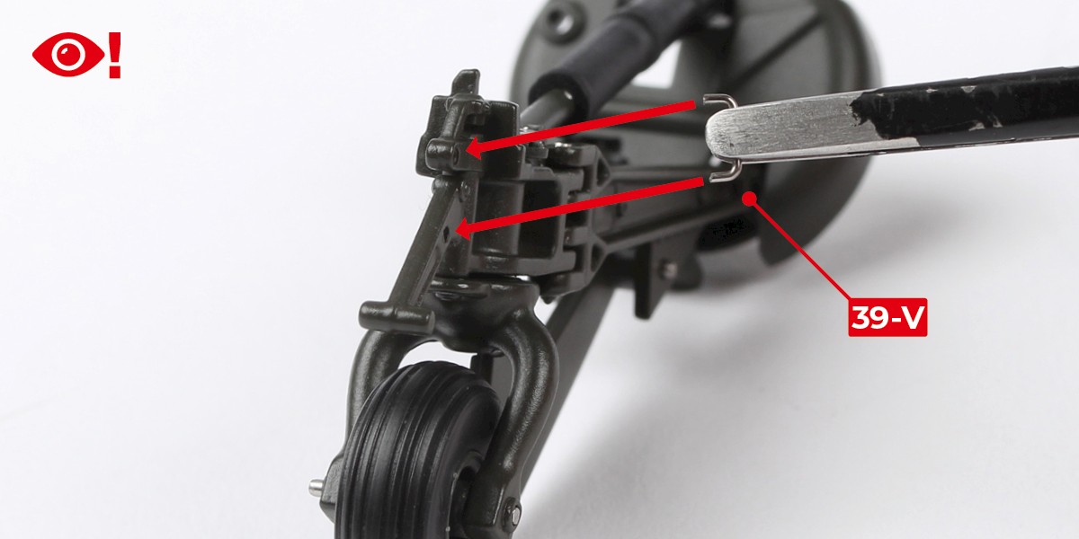
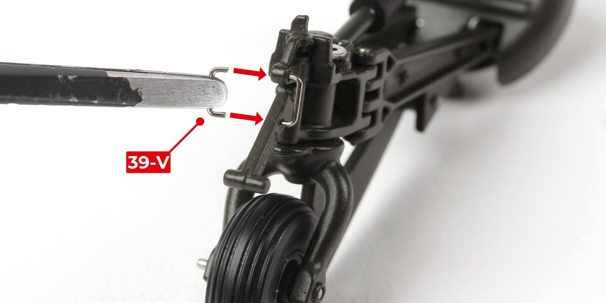
Glue 39-V onto the assembly as shown, then repeat on the other side with another 39-V.
You will need to adjust the position of both parts before the glue dries.
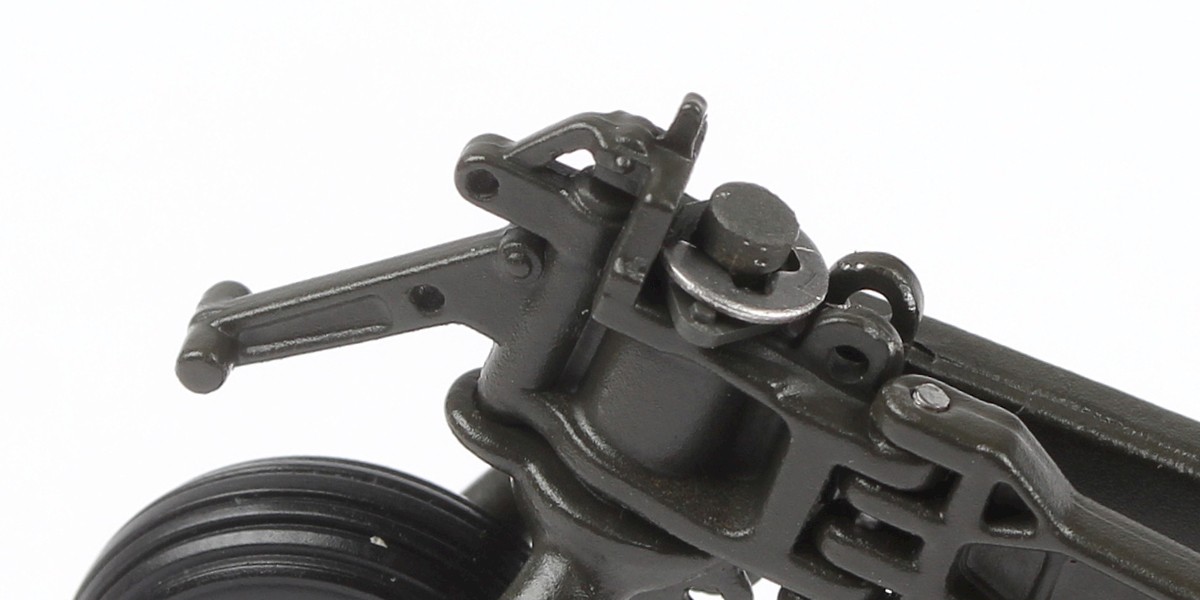
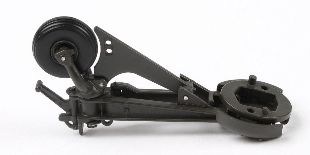
Step 22
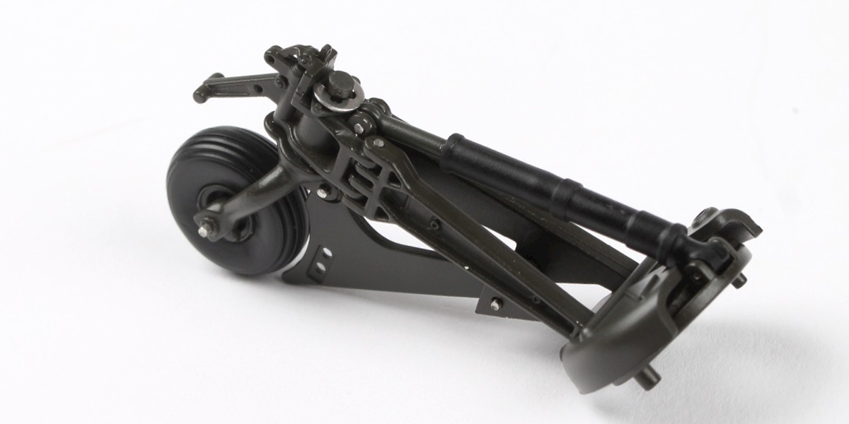
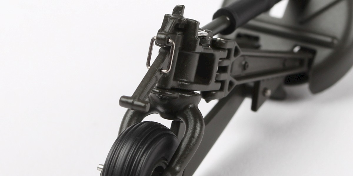
The parts should look like this once in place.
Step 23
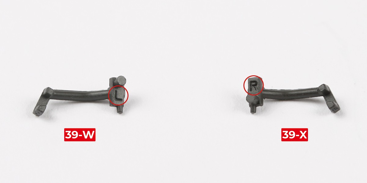
Take 39-W (marked 'L') and 39-X (marked 'R').
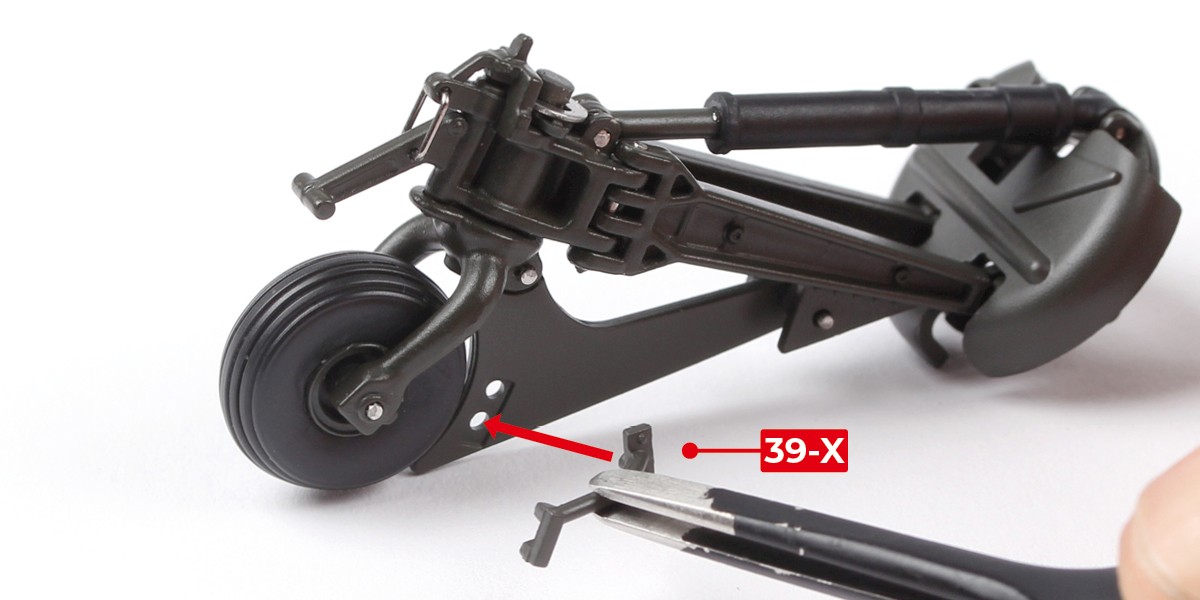
Step 24
Fit 39-X onto the assembly.
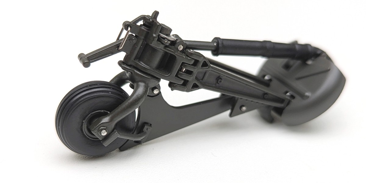
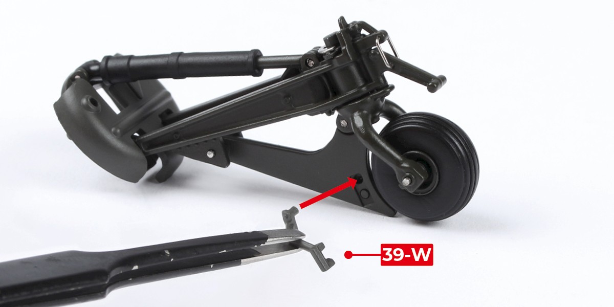
Step 25
Fit 39-W onto the other side.

STAGE COMPLETE