
Advice from the experts
Spare screws are included with each part. Occasionally, you may be instructed to keep spare or unused screws for a later stage. Keep these spares in a safe place and label them correctly.
Please make sure you don’t mix up the screws. They look quite similar, but the threads do vary slightly. Using the wrong screws may damage the parts. Only use the correct size screwdriver that fits the screw head firmly.
When securing parts together using multiple screws, fit each screw loosely to ensure all the parts are correctly aligned before gently tightening them firmly, but not overtight, in the order in which you placed them.
The screwdriver can be magnetized by stroking it with a magnet (fridge magnet, etc.) enabling it to hold the screws and make assembly easier.
If a screw is tight going into a metal part, do not force it as you may shear the head off. Remove it and put a tiny smear of Vaseline, soap or light oil on the thread. That will lubricate it and make it easier to tighten.
Some parts will require a little glue for assembly. Please apply glue sparingly and use a cocktail stick so that you don’t use too much nor apply the glue too heavily. We recommend superglue gel or Extra Thin Liquid modeling glue. Where possible, parts should be test-fitted in place before gluing.
Make sure you have good ventilation when using adhesives and to replace caps firmly.
Use a magnet to help find screws that have fallen on the floor.
Use masking tape to hold parts temporarily in place.
Cut parts from a sprue (framework) with side cutters or a craft knife. Side cutters tend to be easiest.
During the course of this build, you will receive many pieces that you will assemble immediately – following the instructions in the corresponding stage – and other pieces that you should store safely to one side, for use in future assembly stages.
Always protect the paint finish on components by placing a cutting mat, sheet of white paper or soft cloth on your work surface.
When plugging cables in, ensure the power is switched off. Tweezers can be used to fit the PVC cables by gripping carefully around 5mm from the end of the cable. If a cable needs to be removed from a socket, do not pull on the cable as this could damage the connection. Grip the plug with tweezers to remove it.
Left and Right! When building your AH-64 Apache, the left- or right-hand side refers to that side as if you are sitting in the cockpit.
![]() When you see this symbol, pay attention to the instruction text in bold and check the orientation of the parts in the image as this will be particularly important for assembly in later stages.
When you see this symbol, pay attention to the instruction text in bold and check the orientation of the parts in the image as this will be particularly important for assembly in later stages.
WARNING: Some parts are assembled using magnets. These magnets can cause serious injury if they are swallowed. Keep away from children. If you suspect a magnet has been swallowed, seek medical help straight away.
This is not a toy. Not suitable for children under 14 years old due to small parts. Adult supervision required.
PARTS LIST
| 1-A x2 | 1-G | 1-M |
| 1-B | 1-H | 1-N |
| 1-C | 1-I | 1-P |
| 1-D | 1-J | 1-Q |
| 1-E x2 | 1-K | AP x2 |
| 1-F x2 | 1-L | EP x7 |

Step 1
Push 1-L onto 1-P.

Step 2
Push 1-K into 1-Q.

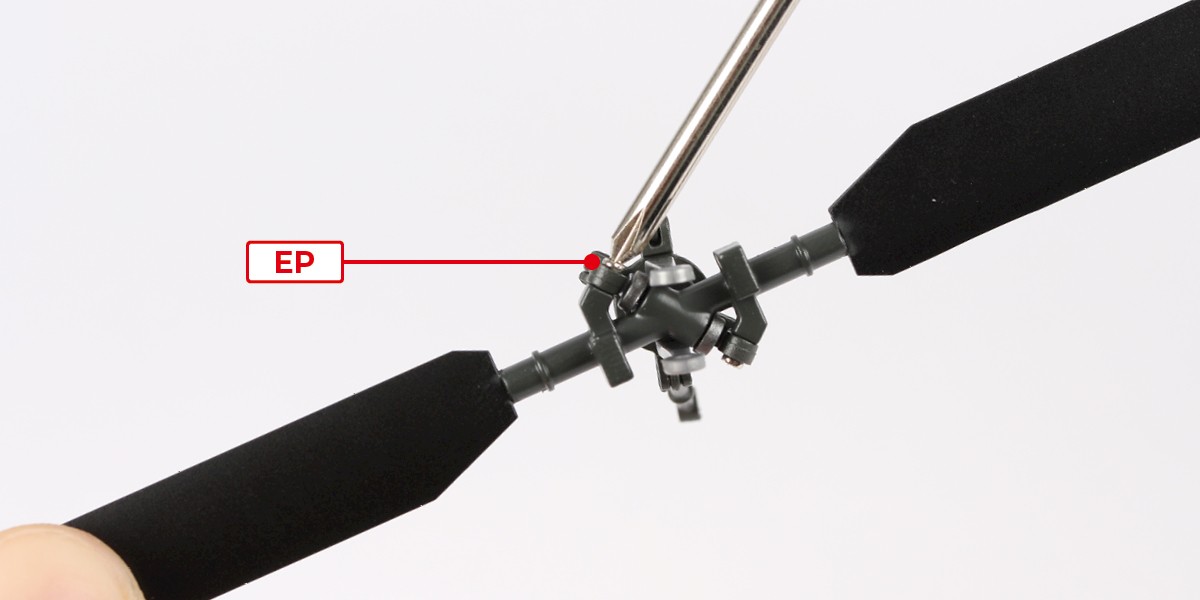
Step 3
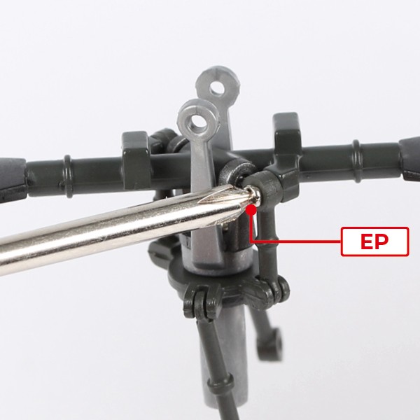
Place 1-G onto 1-K and 1-Q.
Screw the parts together using 2x EP.

Step 4
Place 1-M onto 1-K.
The ball bearings should be facing upwards.


Step 5
Press 1-N onto 1-M.

Step 6
Push 1-C and 1-D into the positions shown.

Step 7
You will now start building the tail rotor.
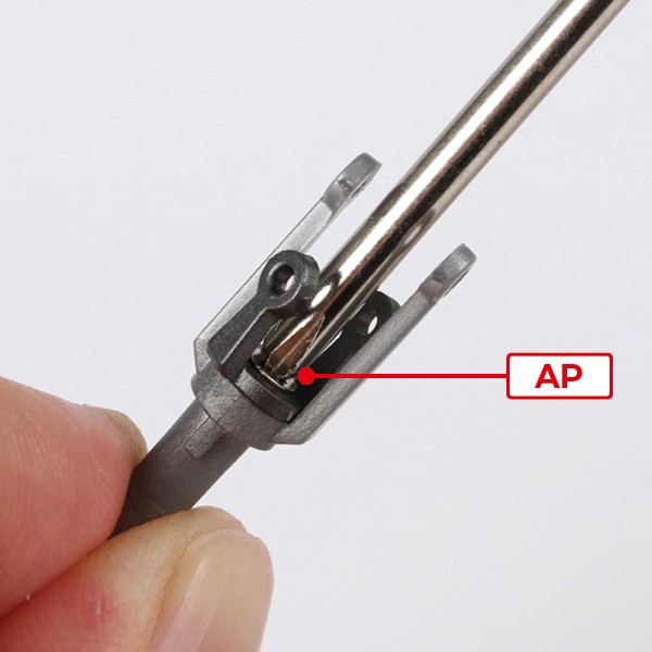
Place 1-B into 1-H.
Screw the parts together using 1x AP.

Step 8
Push 1-H through 1-J.
Make sure the parts are aligned as shown.


Step 9
Push 2x 1-E into 1-J, aligning the parts as shown.

Step 10
Push 2x 1-F into 1-J, aligning the parts as shown.

Step 11
Push 1x 1-A into the assembly.

Step 12
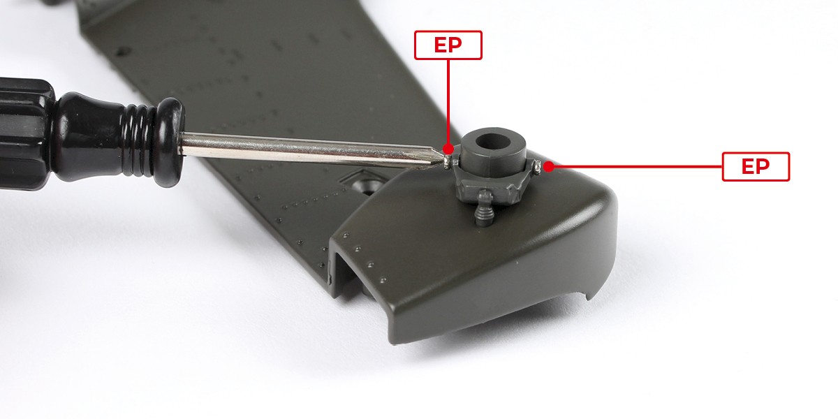
Align 1-F over the screw hole.
Screw the parts together using 1x EP.

Step 13
Repeat on the other side to align 1-F with the screw hole.
Screw the parts together using 1x EP.
Step 14
Push the remaining 1-A on top.

Step 15
Align both 1-E over the screw holes.

Step 16
Screw the parts together using 2x EP.

STAGE COMPLETE
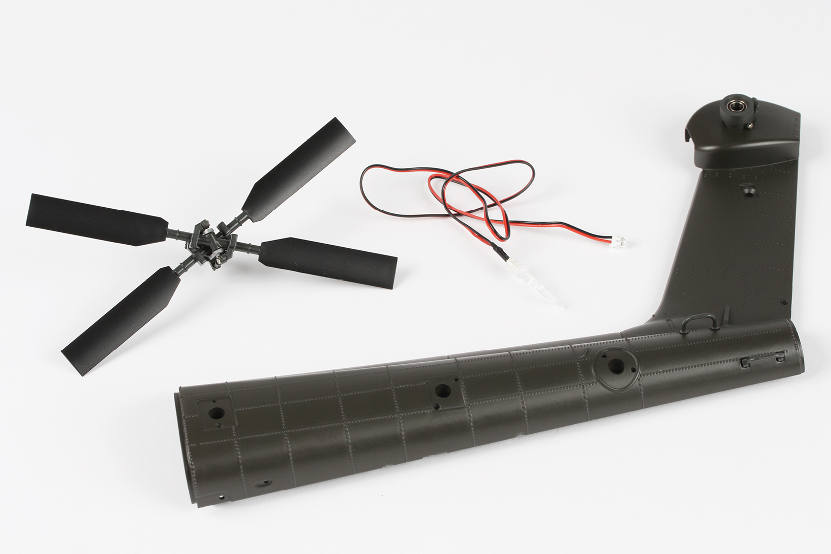
PARTS LIST
| 2-A | 2-G | 2-M | 2-T |
| 2-B | 2-H | 2-N | 2-U x3 |
| 2-C | 2-I | 2-P | 2-V |
| 2-D x2 | 2-J | 2-Q | 2-W |
| 2-E | 2-K | 2-R | BM x3 |
| 2-F | 2-L | 2-S |

Step 1
Prepare parts 2-D, 2-I, and 2-P as shown.

Step 2
Glue 2-D to 2-P.

Step 3
Glue the remaining part 2-D to the opposite side.
Glue 2-I into the central recess.


Step 4
Apply a little glue to 2-N as shown by the red lines.

Step 5
Fix 2-P in place.

Step 6
Glue 2-D to 2-N.


Step 7
Repeat on the opposite side.

Step 8
Push 2-Q through the opening as shown.

Step 9
Glue 2-Q to 2-N.


Step 10
Glue the other ends of 2-Q into place.

Step 11
Glue 2-K to 2-P.
Glue 2-I to 2-P.


Step 12
Glue and push 2-L onto 2-P.

Step 13
Attach 2-R as shown

Step 14
Attach 2-S to the opposite side.

Step 15
Glue and attach 2-C.

Step 16
Glue 2-A as indicated and fix in place.
Glue and attach 2-B.


Step 17
Attach 2-E and 2-F, checking that they point inwards.

Step 18
You will now start building the main rotor blade.
Place 2-W onto 2-J. 2-J is marked with a '1' as indicated.

Step 19
Place 2-H on top.

Step 20
Push 2x 2-U through 2-H and 2-J.


Step 21
You will now attach the tail rotor.
Thread 2-M through 2-G all the way through.


Step 22
Attach 2-T as shown.

Step 23
Place the assembly from the previous step onto the assembly from stage 01, step 6.

Step 24
Screw the parts together using 2x BM.

Step 25
Take the tail rotor assembly (stage 01, step 15) and push it into place. Twist as you press to make sure it connects with the motor.

Step 26
Insert 2x AAA batteries into 2-V. Connect cable B. The rotors should spin.
Disconnect the cable after testing.

Step 27
Connect 1-P (cable A) to 2-V. The LED should light up.
Disconnect the cable then remove the batteries from 2-V.

STAGE COMPLETE
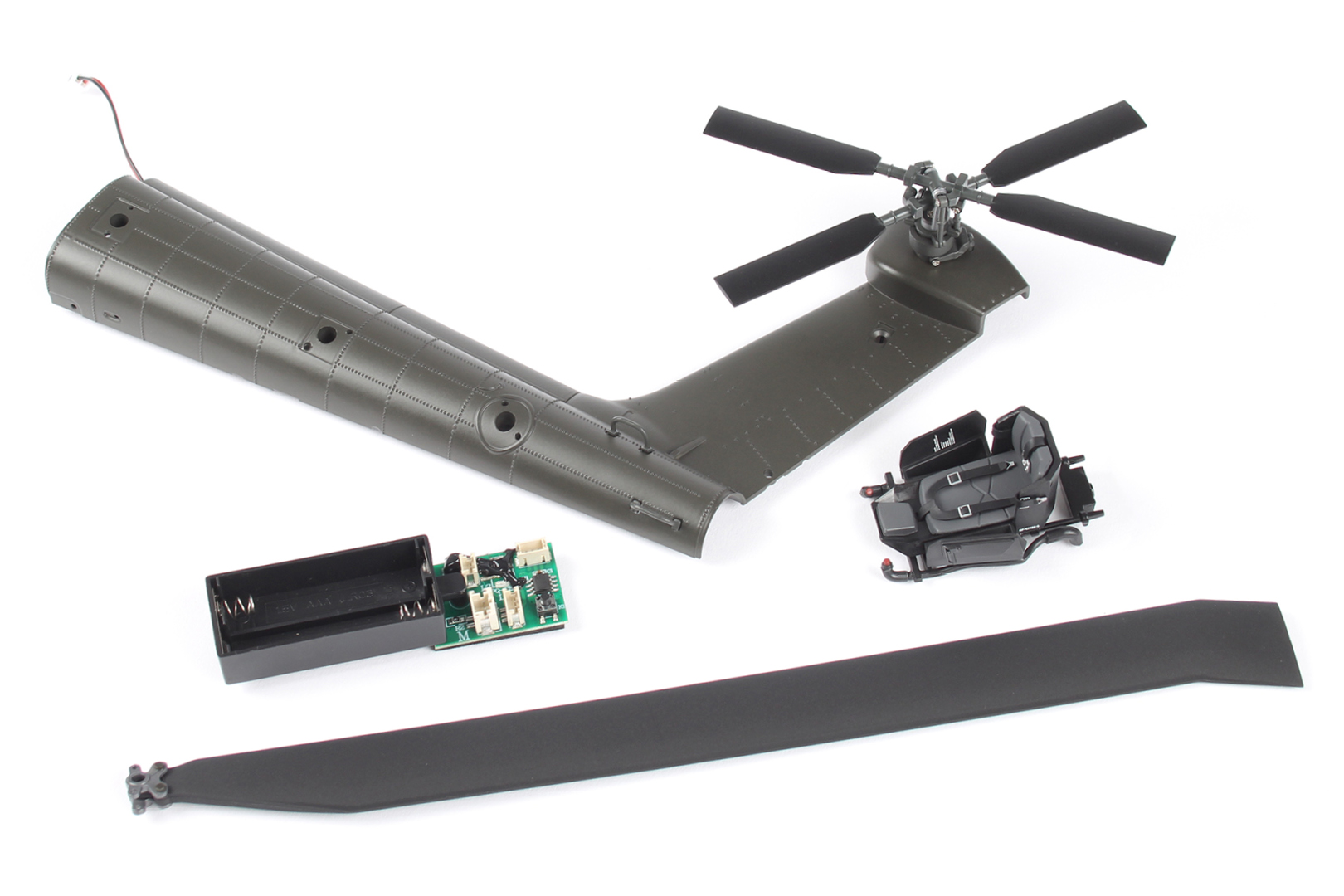
PARTS LIST
| 3-A | 3-G | 3-N |
| 3-B | 3-H | 3-P |
| 3-C | 3-J | AM x2 |
| 3-D | 3-K | BP x3 |
| 3-E | 3-L | |
| 3-F | 3-M |

Step 1
Push 3-F into 3-G.

Step 2
The parts should look like this once in place.

Step 3
Push 3-G into 3-P.
Screw the parts together using 2x BP.


Step 4
Pair parts 3-A and 3-B with 3-H and 3-J using the image.

Step 5
Glue 3-A into 3-H and 3-B into 3-J.

Step 6
Glue 3-H and 3-J into 3-P.

Step 7
Glue 3-L into 3-P.
Glue 3-M into 3-P.


Step 8
Glue 3-N into 3-P.

Step 9
Glue 3-K into 3-P.

Step 10
Glue 3-D into 3-P.

Step 11
Align 3-C with 3-P as shown.

Step 12
Push 3-C onto 3-P, then glue 3-E onto 3-P as shown.


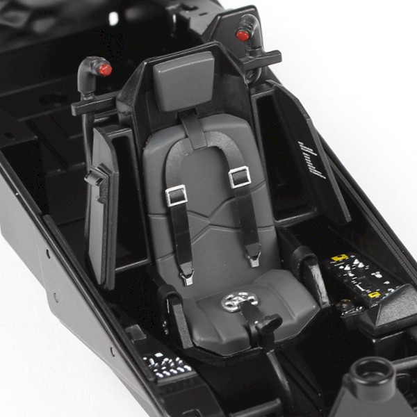
Step 13
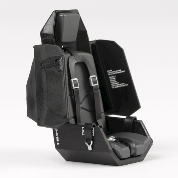
Place the co-pilot seat (stage 02, step 16) into 3-P.
Take care not to damage any parts.
Step 14
Screw the parts together using 1x AM.
STAGE COMPLETE
PARTS LIST
| 4-A | 4-G x2 | 4-N |
| 4-B | 4-H | 4-P |
| 4-C | 4-J | CP x3 |
| 4-D | 4-K | DP x2 |
| 4-E | 4-L | |
| 4-F | 4-M |

Step 1
Insert 2x AAA batteries into the circuit board( stage 02). Connect 4-P (cable C). The LEDs should light up.
Disconnect the cable and remove the batteries after testing.

Step 2
Place 4-P onto 4-B. Screw the parts together using 2x CP.

Step 3
Push 4-M into 4-A.

Step 4
Thread cable C through 4-A.
Join 4-A and 4-B. Press together.


Step 5
Press 4-C and 4-D into 4-A.

Step 6
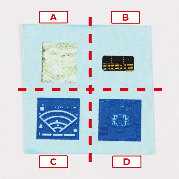
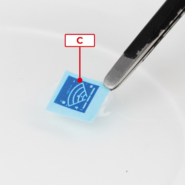
Cut 4-N into four sections.
Soak each decal in water for 30 seconds before applying.
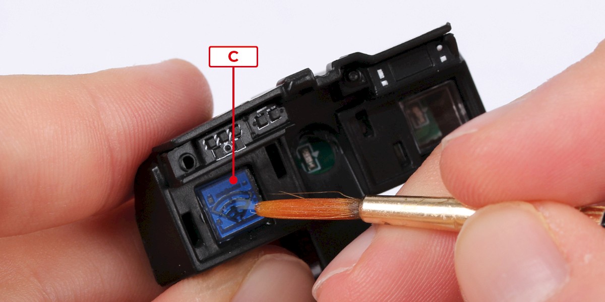
Step 7
Apply decal C to the assembly. Check the orientation is correct.
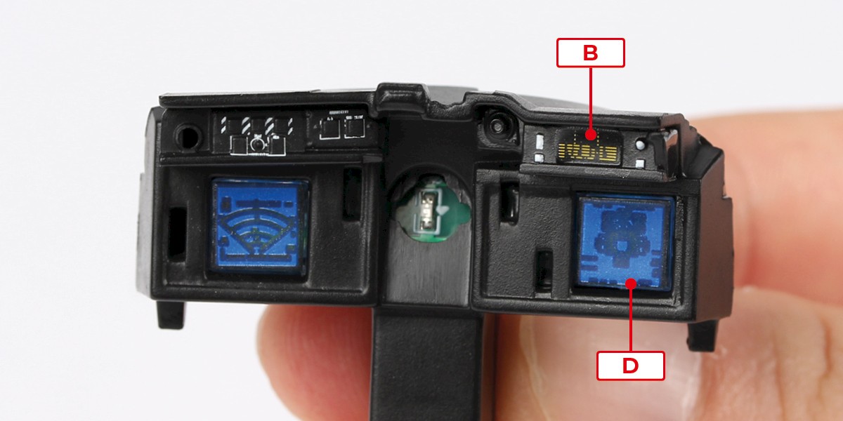
Step 8
Apply decals D and B to the assembly as shown.
Check the orientation carefully.
Step 9
Place parts 4-G underneath 4-E and 4-F.

Step 10
Glue 4-E and 4-F onto 4-A.
Take care not to damage or get glue on the decals.

Step 11
Place 4-J underneath 4-H. Study the picture carefully to ensure the correct orientation.

Step 12
Apply decal A to 4-K then place it underneath 4-H.

Step 13
Push 4-H onto 4-L.

Step 14
Push 4-L into 4-A.

Step 15
Thread cable C through the cockpit frame assembly (stage 03, step 14).

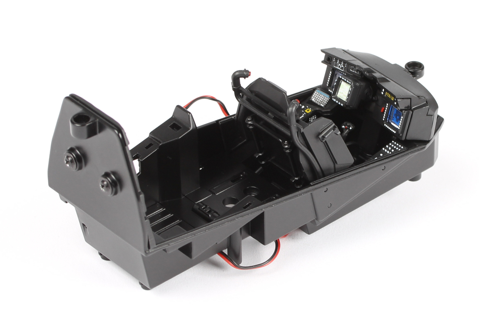
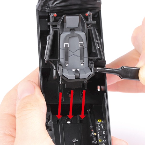
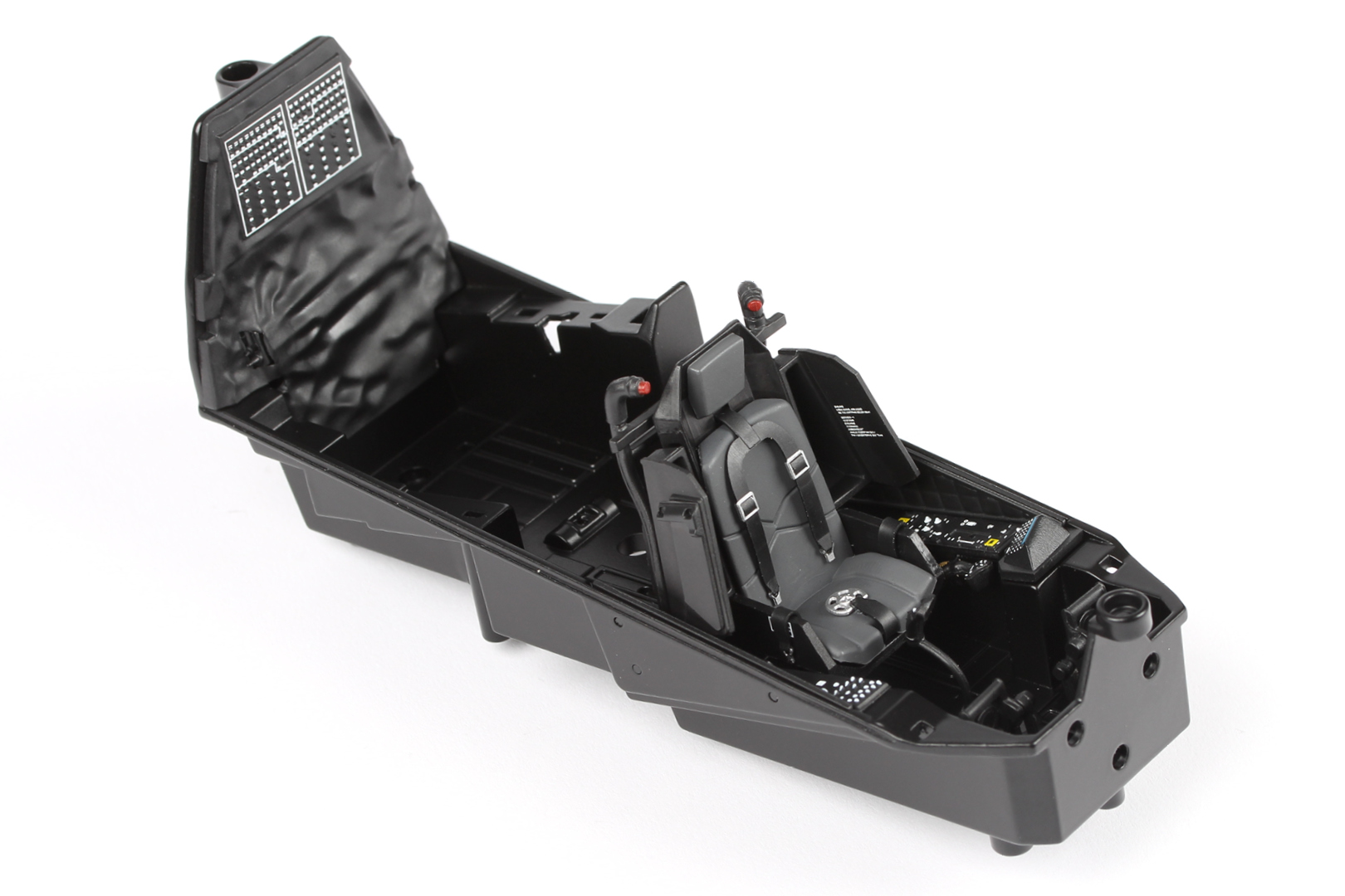
Step 16
Carefully push the assembly into the cockpit frame.
Take care not to damage any of the fragile parts on the cockpit frame.

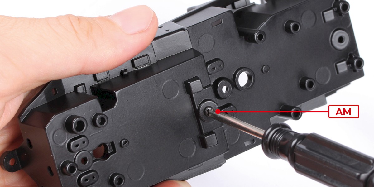
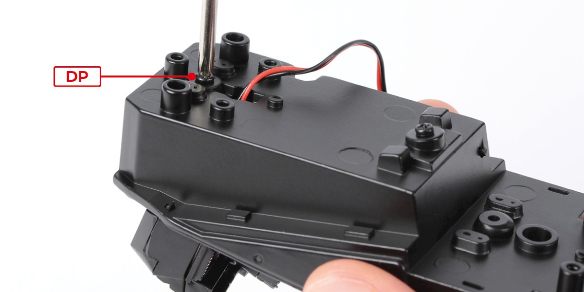
Step 17
Screw the parts together using 1x DP.
STAGE COMPLETE