
Pack 06
BUILD INSTRUCTIONS
Advice from the experts
Spare screws are included with each part. Occasionally, you may be instructed to keep spare or unused screws for a later stage. Keep these spares in a safe place and label them correctly.
Please make sure you don’t mix up the screws. They look quite similar, but the threads do vary slightly. Using the wrong screws may damage the parts. Only use the correct size screwdriver that fits the screw head firmly.
When securing parts together using multiple screws, fit each screw loosely to ensure all the parts are correctly aligned before gently tightening them firmly, but not overtight, in the order in which you placed them.
The screwdriver can be magnetized by stroking it with a magnet (fridge magnet, etc.) enabling it to hold the screws and make assembly easier.
If a screw is tight going into a metal part, do not force it as you may shear the head off. Remove it and put a tiny smear of Vaseline, soap or light oil on the thread. That will lubricate it and make it easier to tighten.
Some parts will require a little glue for assembly. Please apply glue sparingly and use a cocktail stick so that you don’t use too much nor apply the glue too heavily. We recommend superglue gel or Extra Thin Liquid modeling glue. Where possible, parts should be test-fitted in place before gluing.
Make sure you have good ventilation when using adhesives and to replace caps firmly.
Use a magnet to help find screws that have fallen on the floor.
Use masking tape to hold parts temporarily in place.
Cut parts from a sprue (framework) with side cutters or a craft knife. Side cutters tend to be easiest.
During the course of this build, you will receive many pieces that you will assemble immediately – following the instructions in the corresponding stage – and other pieces that you should store safely to one side, for use in future assembly stages.
Always protect the paint finish on components by placing a cutting mat, sheet of white paper or soft cloth on your work surface.
When plugging cables in, ensure the power is switched off. Tweezers can be used to fit the PVC cables by gripping carefully around 5mm from the end of the cable. If a cable needs to be removed from a socket, do not pull on the cable as this could damage the connection. Grip the plug with tweezers to remove it.
Left and Right! When building your Goldfinger DB5, the left- or right-hand side refers to that side as if you are sitting in the car.
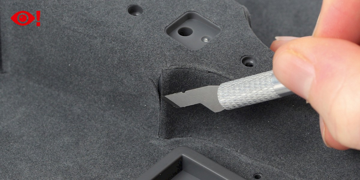
![]() When you see this symbol, pay attention to the instruction text in bold and check the orientation of the parts in the image as this will be particularly important for assembly in later stages.
When you see this symbol, pay attention to the instruction text in bold and check the orientation of the parts in the image as this will be particularly important for assembly in later stages.
WARNING: Some parts are assembled using magnets. These magnets can cause serious injury if they are swallowed. Keep away from children. If you suspect a magnet has been swallowed, seek medical help straight away.
This is not a toy. Not suitable for children under 14 years old due to small parts. Adult supervision required.

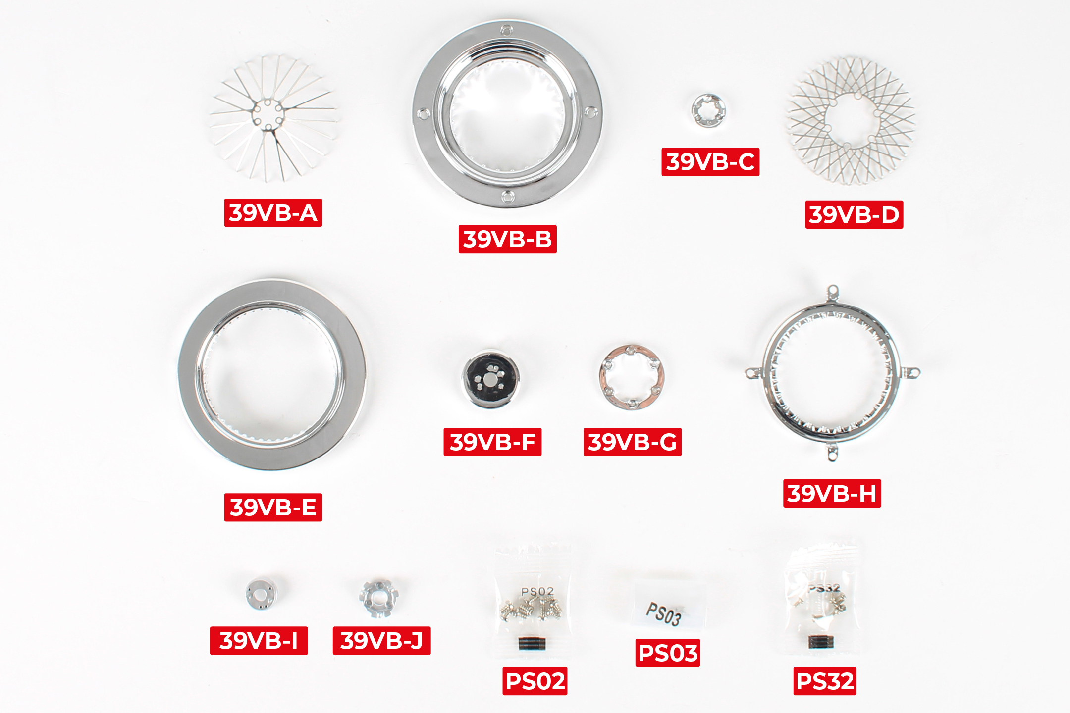
PARTS LIST
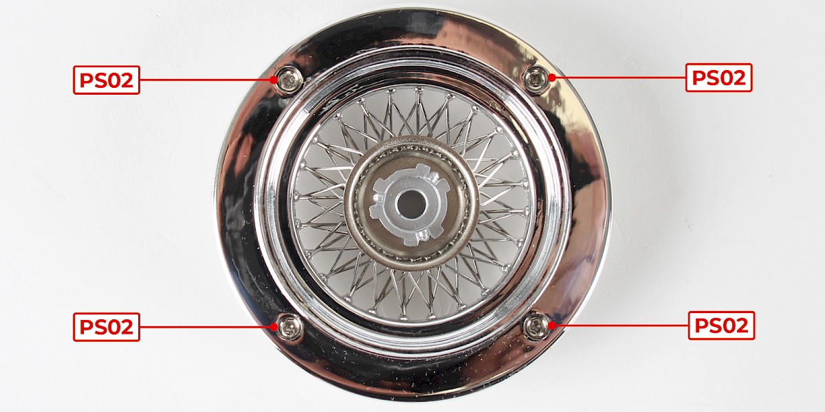
| 39VB-A Outer spokes | 39VB-F Wheel hub back | 9x PS02 screws |
| 39VB-B Inner wheel rim | 39VB-G Inner ring | 4x PS03 screws |
| 39VB-C Outer ring | 39VB-H Spoke retainer ring | 7x PS32 screws |
| 39VB-D Inner spokes | 39VB-I Wheel hub front | |
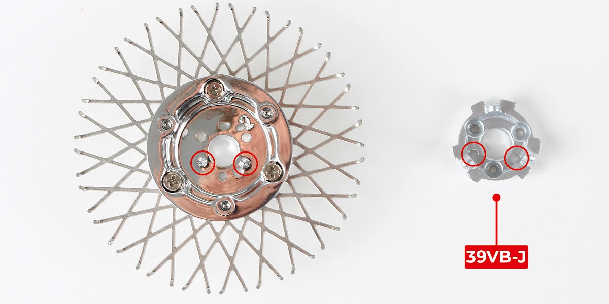
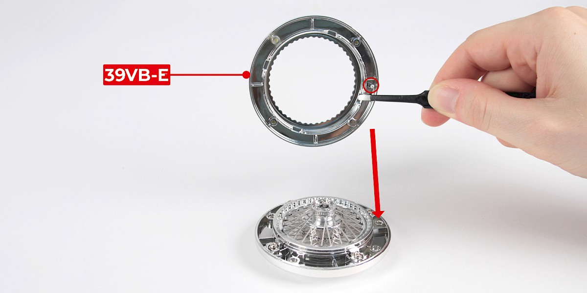
| 39VB-E Outer wheel rim | 39VB-J Rear wheel mount |
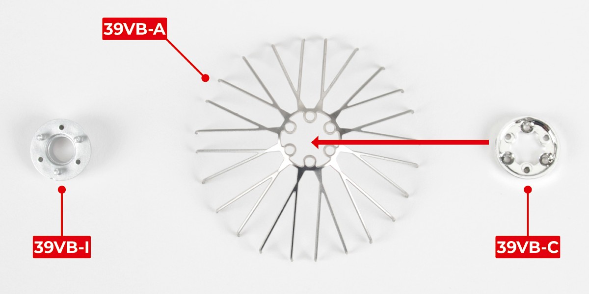
Step 1
Take the wheel hub front (39VB-I), the outer spokes (39VB-A) and the outer ring (39VB-C). Place the outer ring on top of the outer spokes.
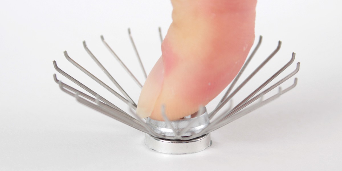
Step 2
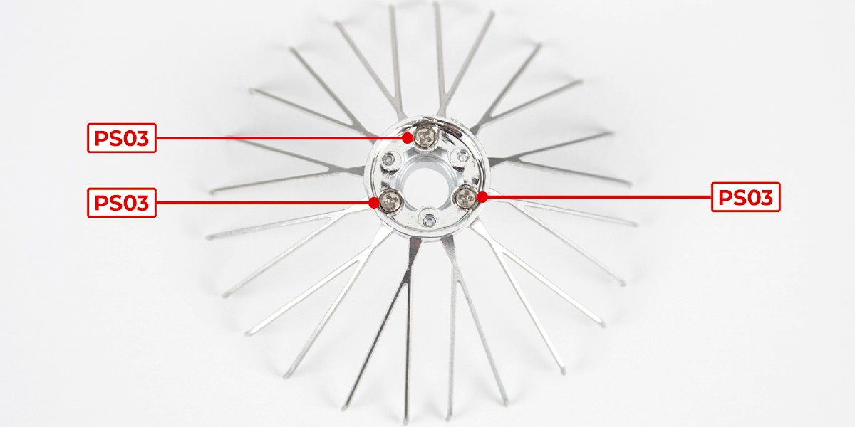
Turn the assembly over and press the wheel hub front into the outer spokes and the outer ring.
Screw the parts together using 3x PS03.
Step 3
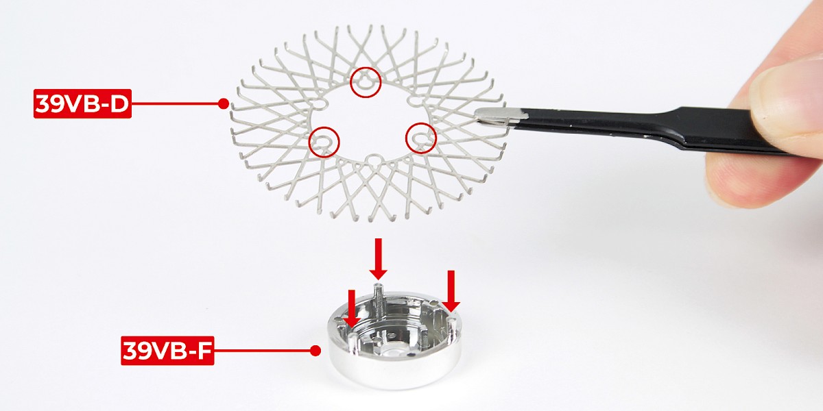
Place the inner spokes (39VB-D) onto the wheel hub back (39VB-F). The ends of the inner spokes must point upwards.
Step 4
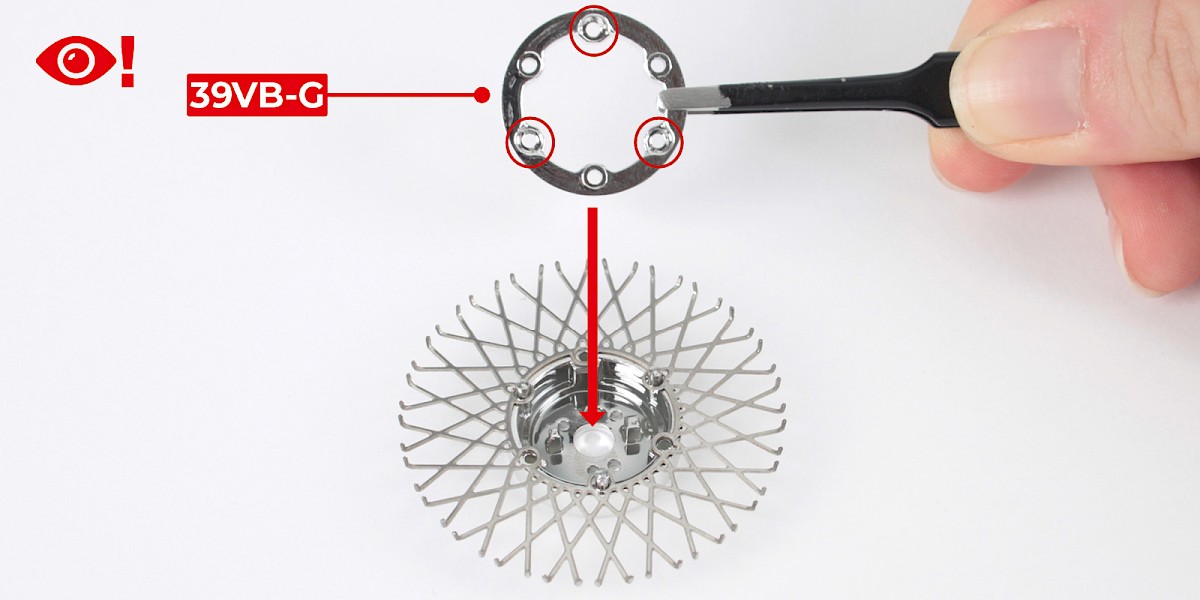
Place the inner ring (39VB-G) on top of the assembly. Check that the screw holes are in the correct position.
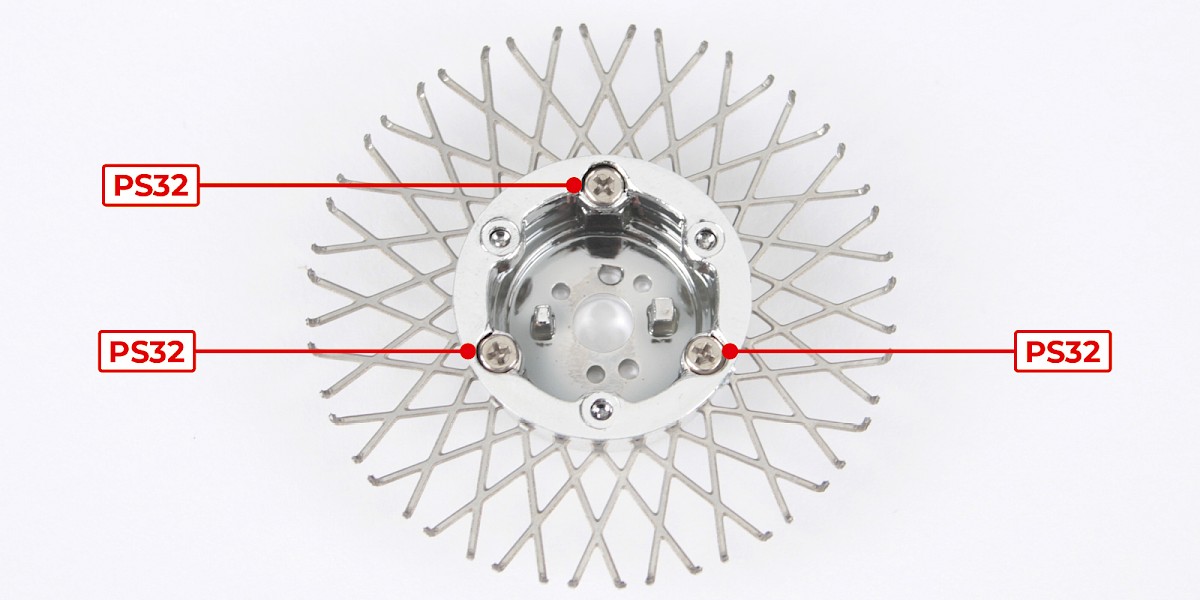
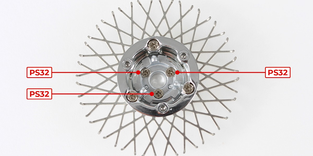
Screw the parts together using 3x PS32.
Step 5
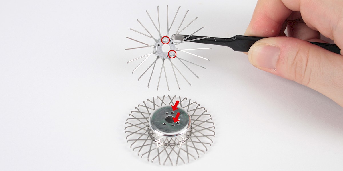
Press the rear wheel mount (39VB-J) onto the wheel hub back.
Screw the parts together using 3x PS32.
Step 6
Place the outer spokes onto the wheel hub back.
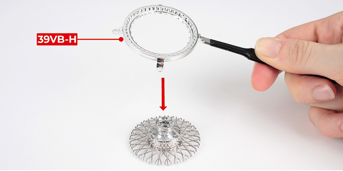
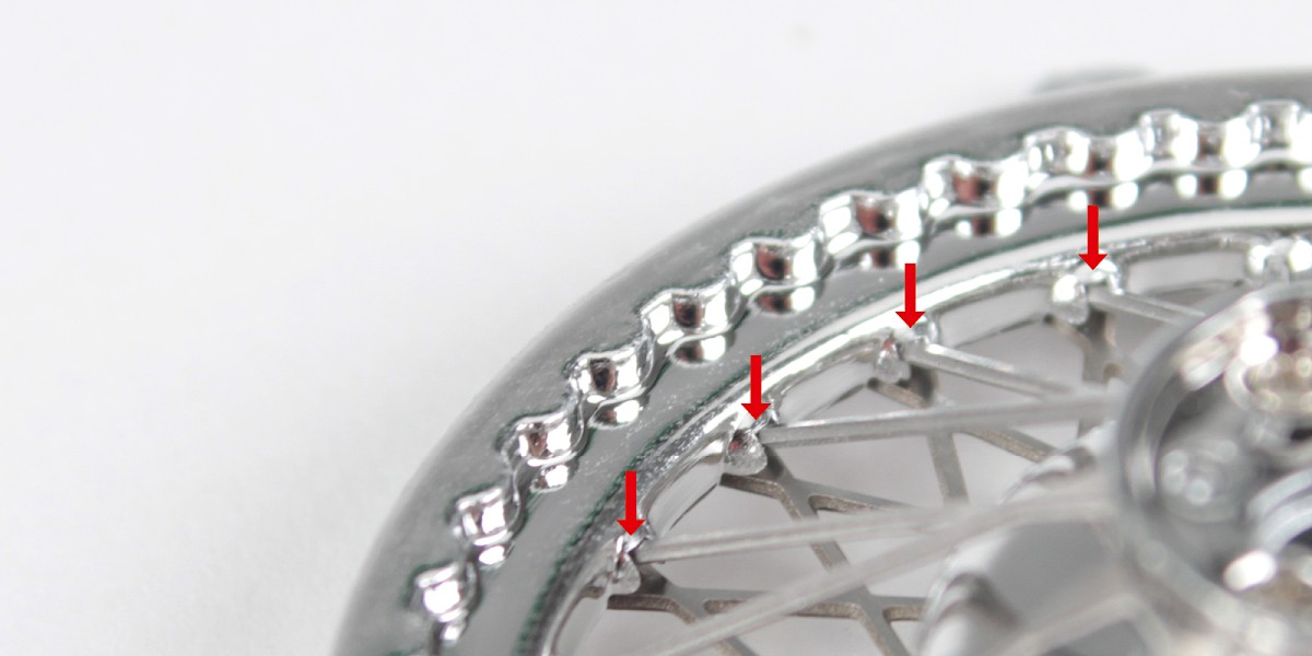
Step 7
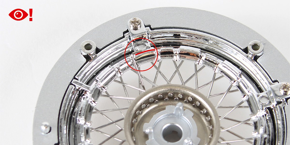
Place the spoke retainer ring (39VB-H) onto the assembly.
Check the outer spokes are correctly in place around the edge.
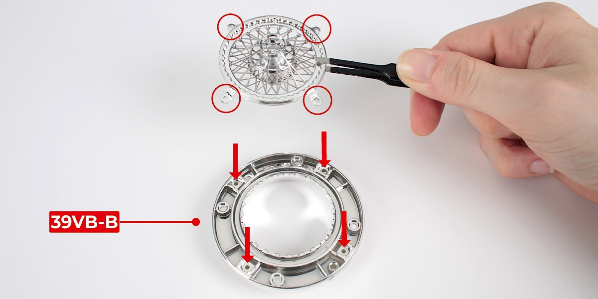
Step 8
Place the assembly onto the inner wheel rim (39VB-B).
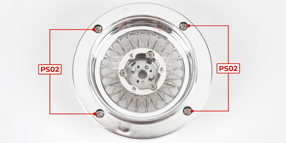
Screw the parts together using 4x PS02.
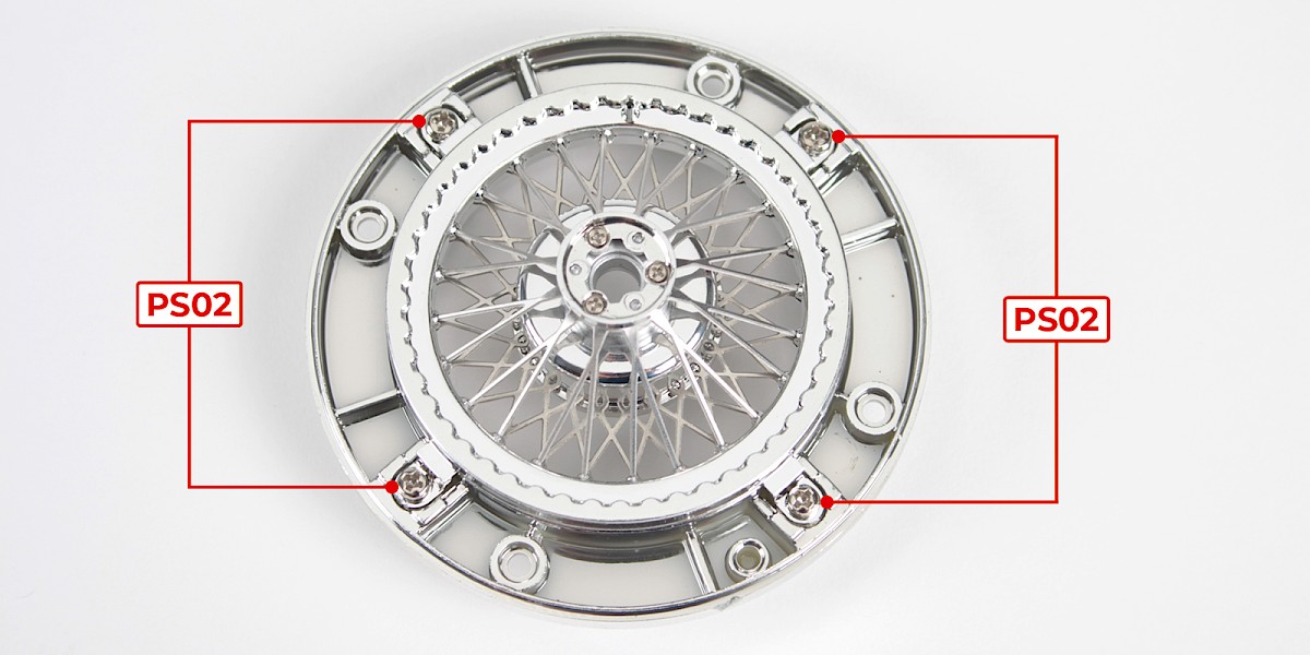
Step 9
Place the outer wheel rim (39VB-E) onto the assembly.
Screw the parts together using 4x PS02.
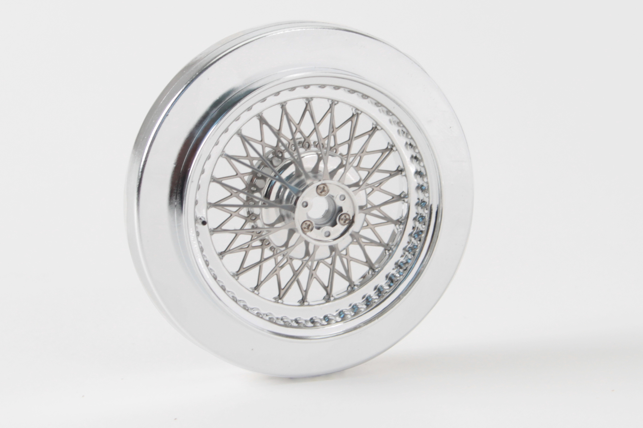
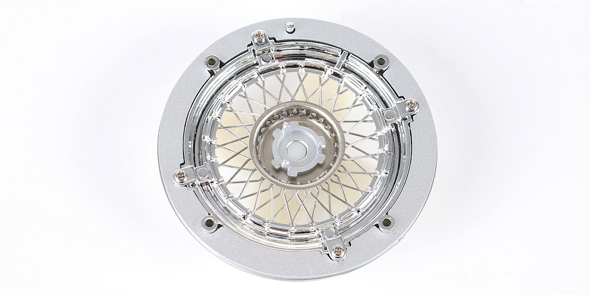
STAGE COMPLETE
PARTS LIST
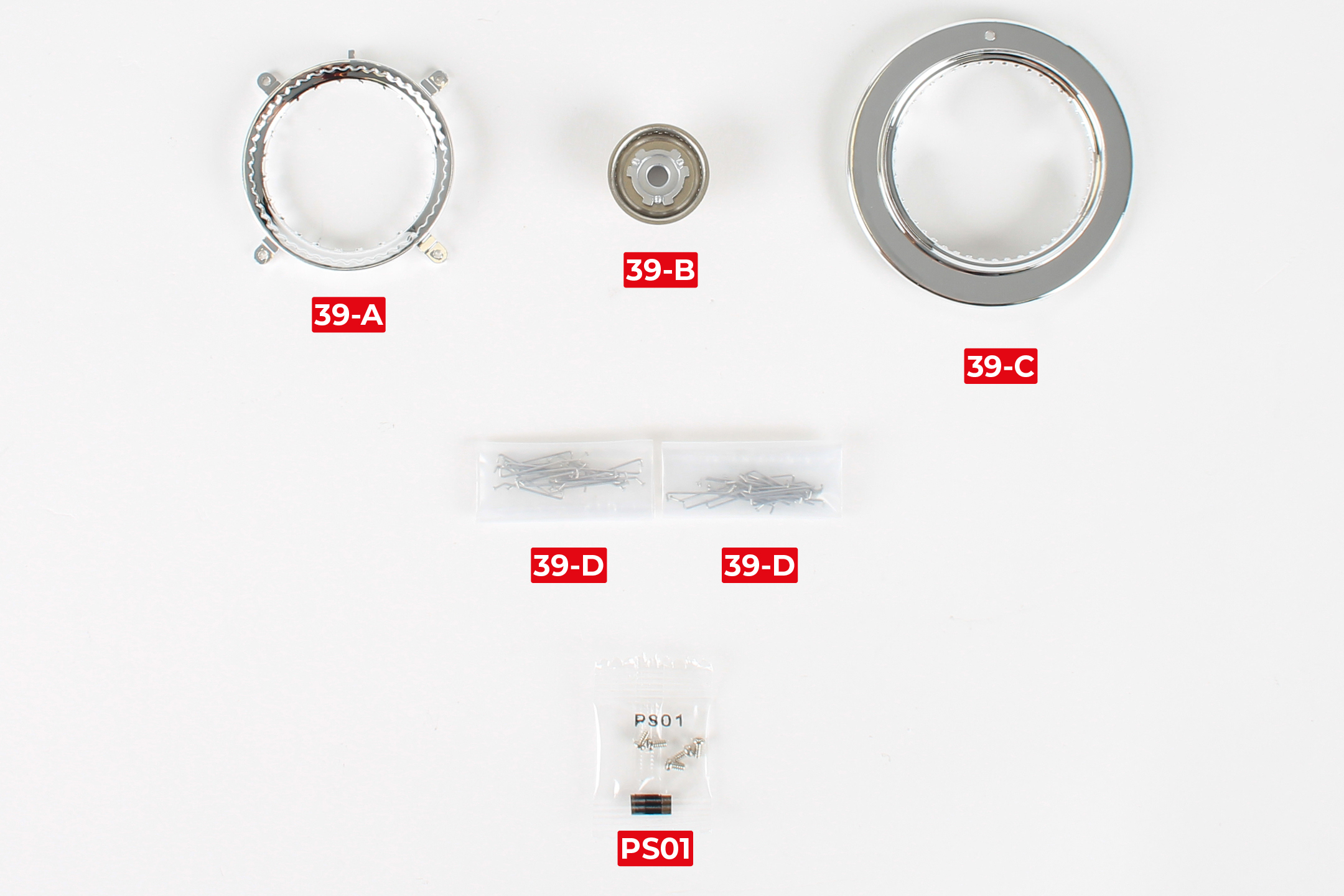
| 39-A Spoke retainer ring | 39-D Spoke x48 |
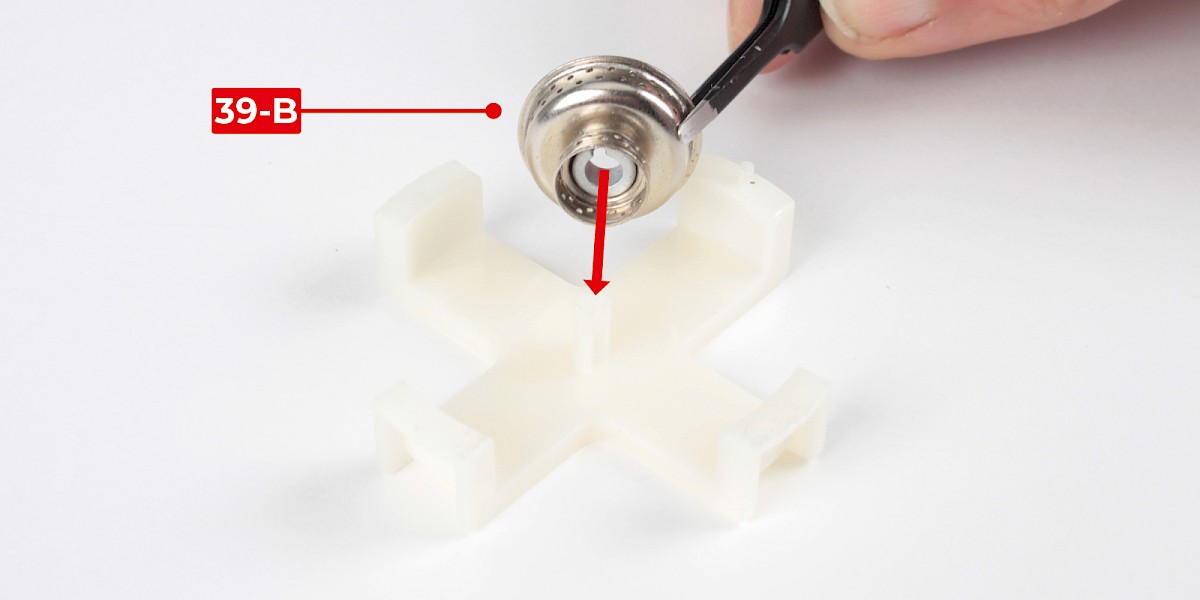
| 39-B Rear wheel centre | 5x PS01 screws |
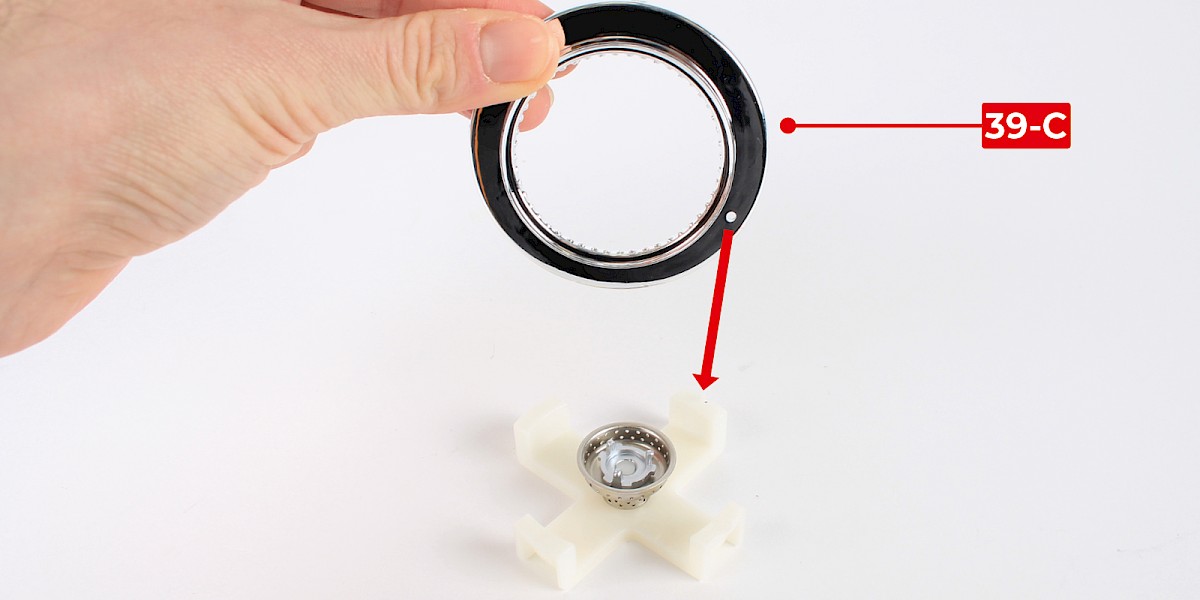
| 39-C Outer wheel rim |
Step 1
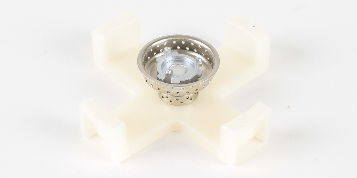
Press the rear wheel centre (39-B) onto the jig (stage 002).
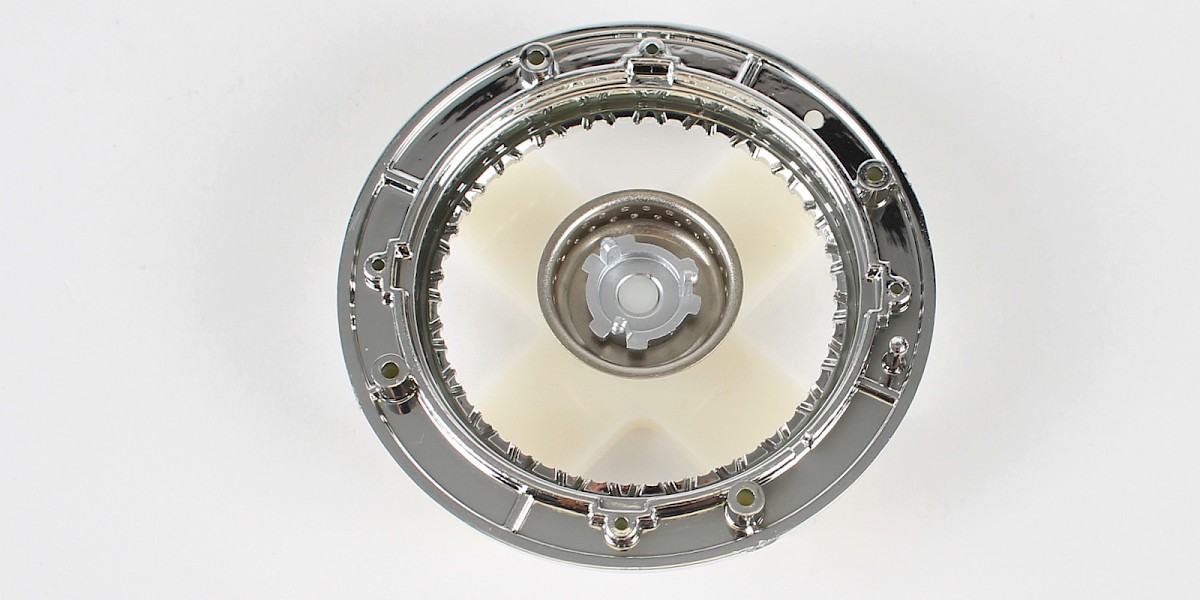
Step 2
Press the outer wheel rim (39-C) onto the jig.
Step 3
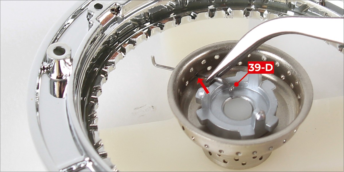
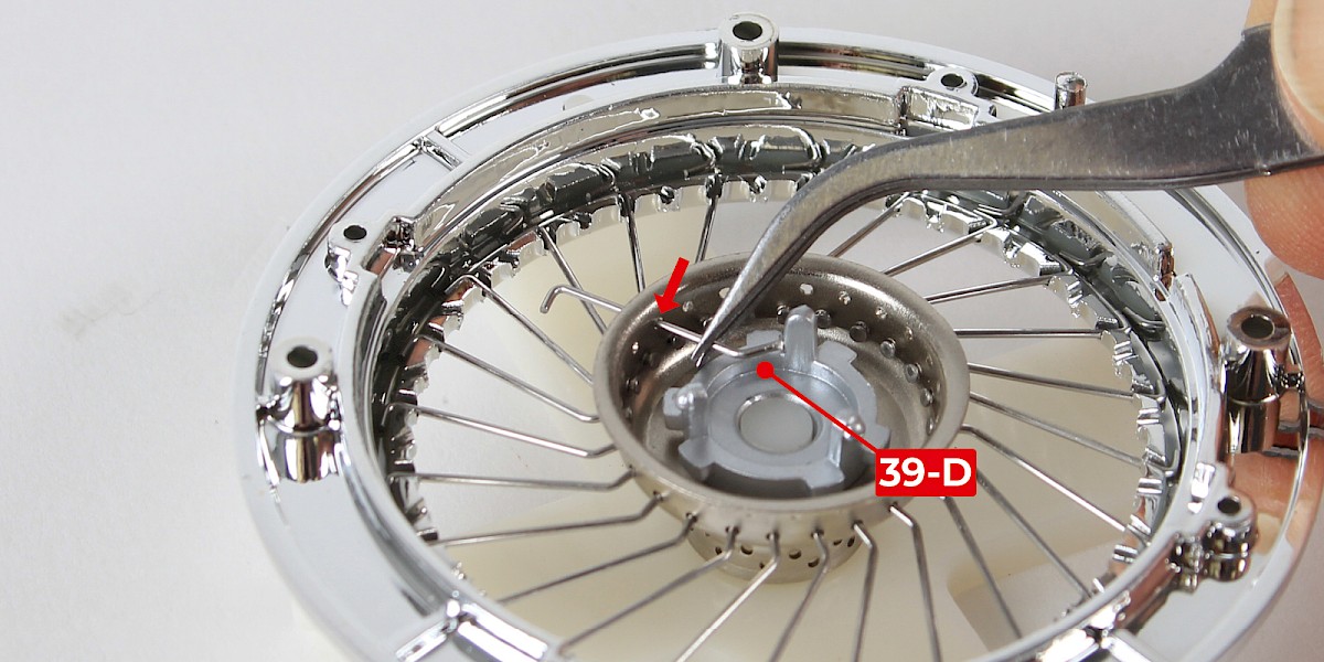
Push a spoke (39-D) through the lower row of holes in the wheel centre.
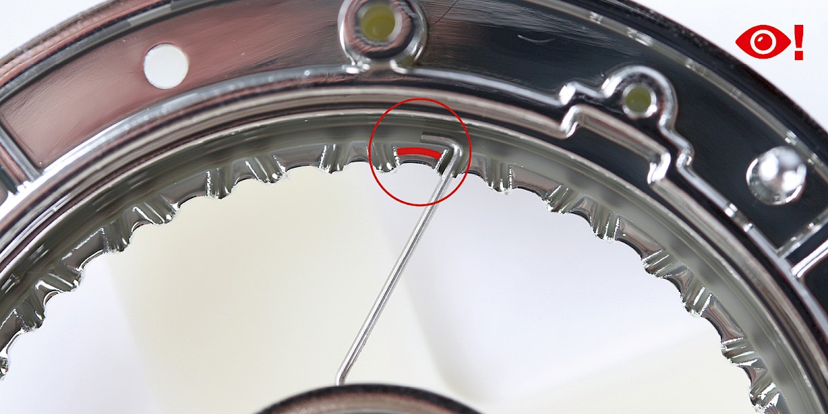
Pull the spoke through the hole. Hook the end of the spoke around the nearest wide tooth. Study the image carefully to make sure the spoke is positioned correctly.
Step 4
Push another spoke through the next hole in the lower row. Hook the end of the spoke around the next wide tooth. Continue to fit the spokes until there are 24 spokes in place.
The tension of the spokes can be adjusted by gently pressing and twisting the wheel centre with your thumb.
Step 5
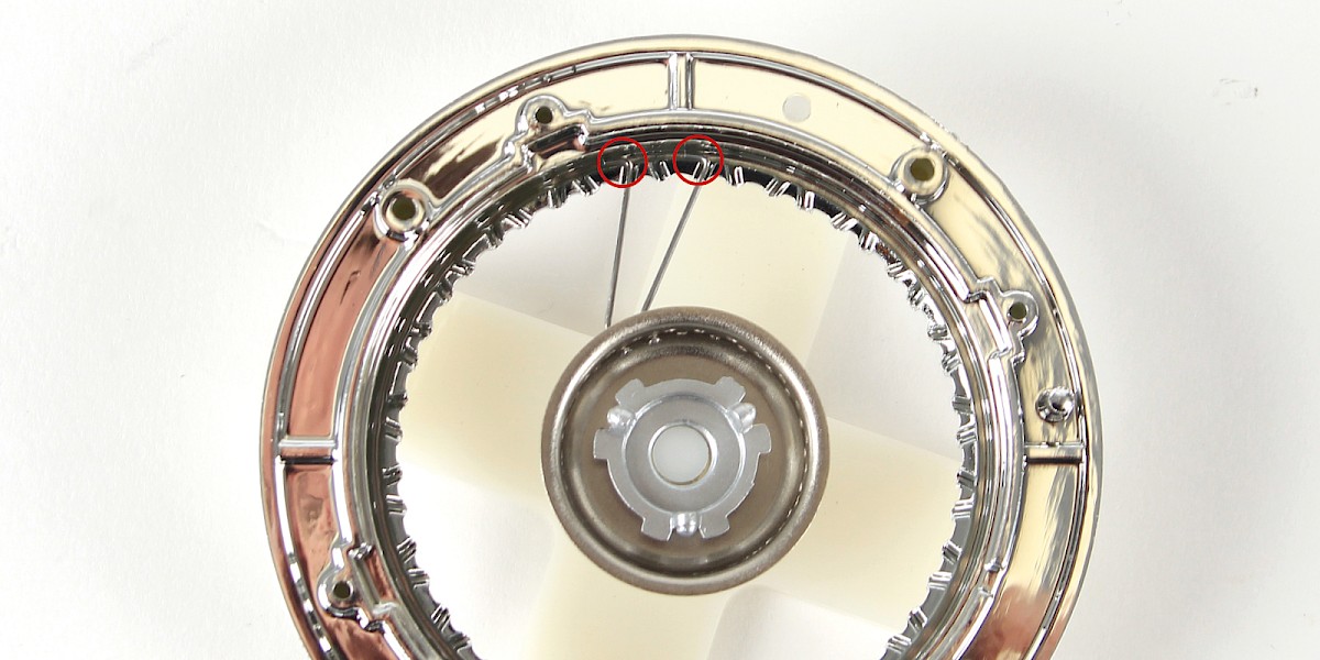
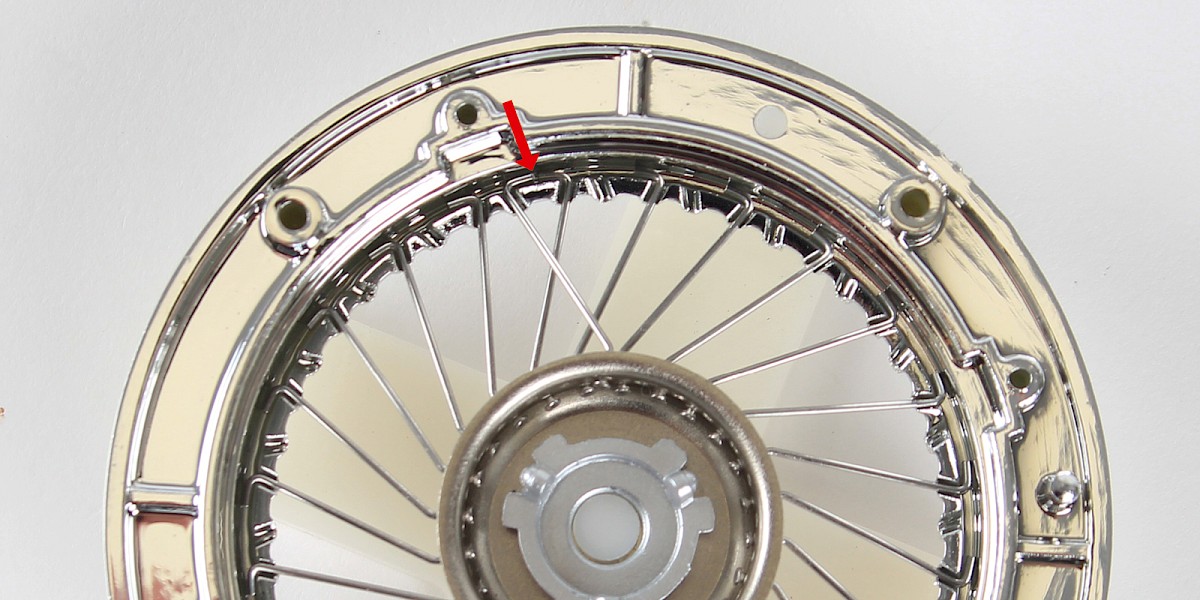
Push a spoke (39-D) through the upper row of holes in the wheel centre.
Hook the end of the spoke around the nearest wide tooth so that the spoke in the upper row faces one of the spokes in the lower row.
Step 6
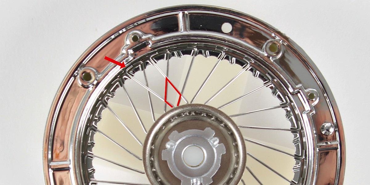
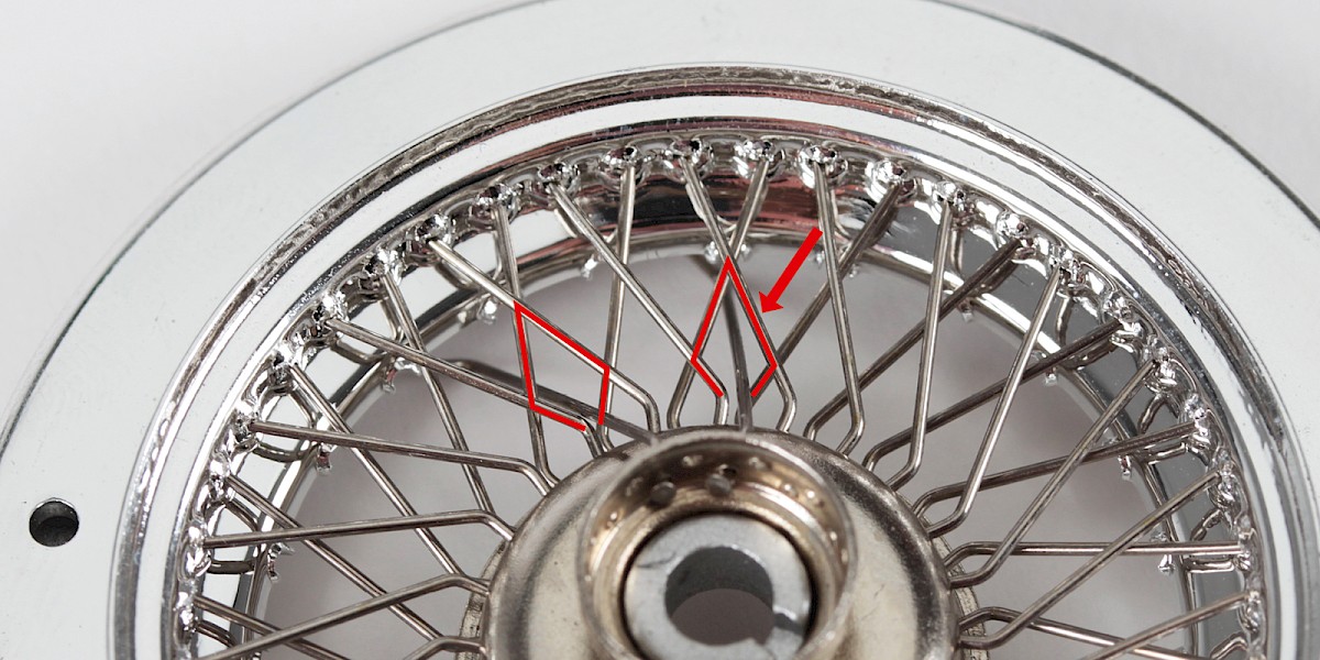
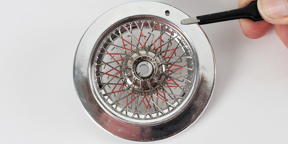
Push another spoke through the next hole in the upper row. Hook the end of the spoke around the next wide tooth. The spokes will create a diamond shape as shown in the image.
Step 7
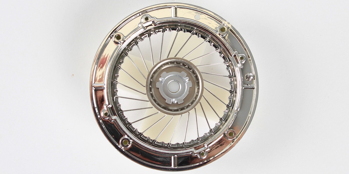
Continue to fit the spokes until there are 24 spokes in the upper row. Carefully check each wide tooth to ensure the spokes are facing in the correct direction.

Step 8
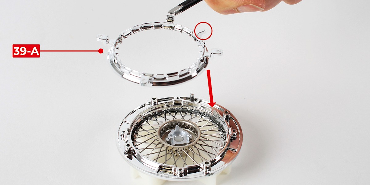
Carefully place the spoke retainer ring (39-A) on top of the assembly.
Screw the parts together using 4x PS01.
STAGE COMPLETE
PARTS LIST
| 40-A Inner wheel rim | 40-D Type B spoke x12 |
| 40-B Spacer ring | 5x PS02 screws |
| 40-C Type A spoke x12 |
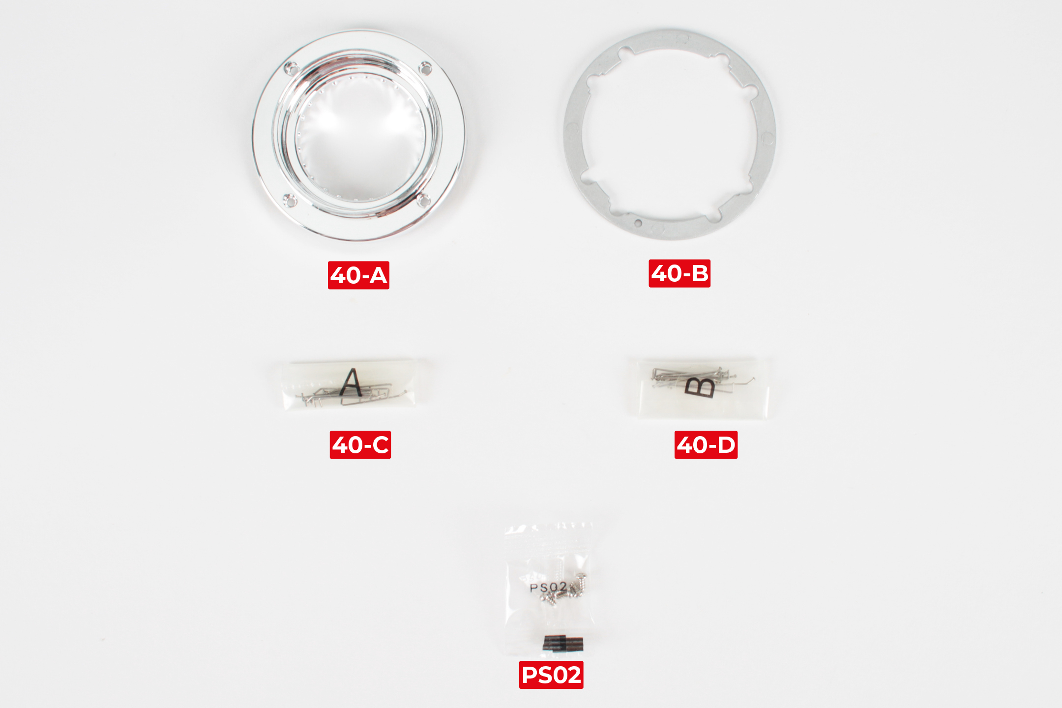
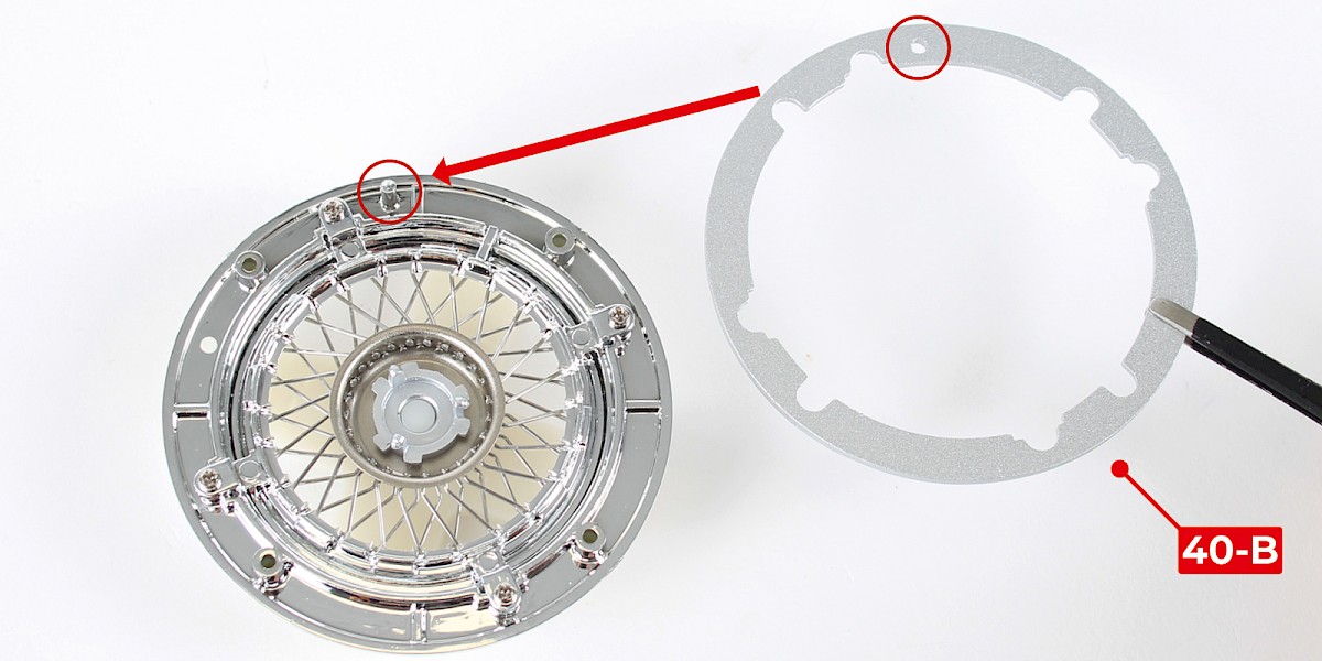
Step 1
Place the spacer ring (40-B) onto the assembly from stage 39.
Step 2
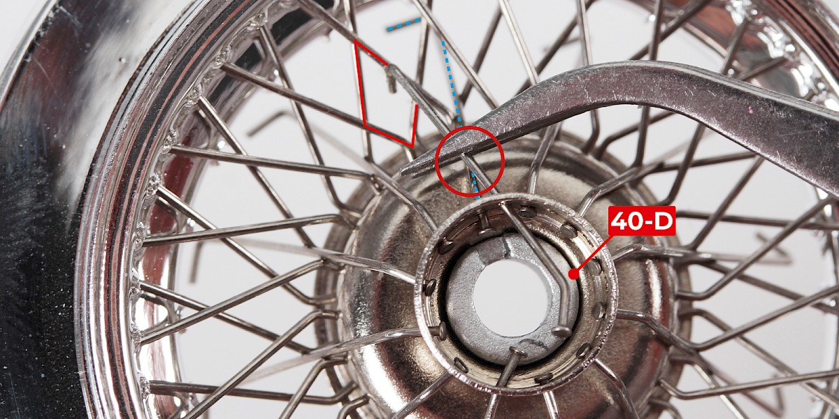
Turn the assembly over and push a type A spoke (40-C) through the lower row of holes in the wheel centre.

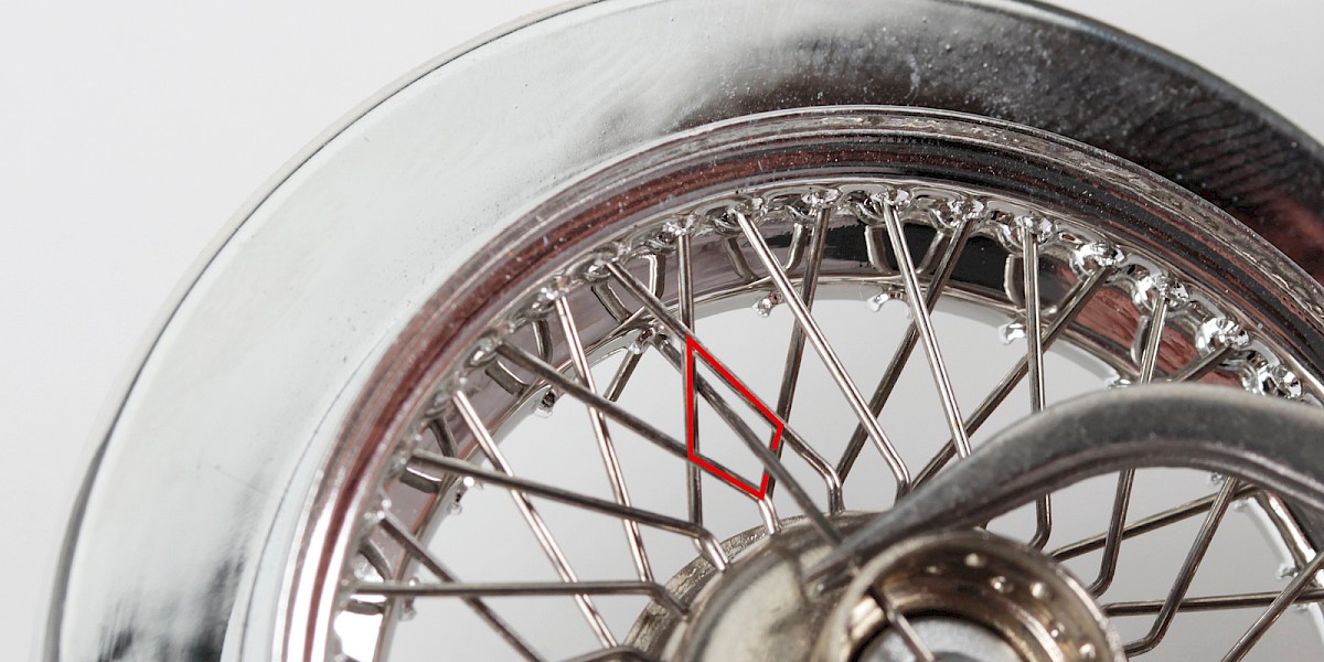
Step 3
Pull the spoke through the hole. Push the end of the spoke through the diamond shape to the left. Push the end of the spoke to the opposite side of the wheel.
Step 4
Turn the assembly over and hook the end of the spoke around a wide tooth. If the spoke will only fit around a narrow tooth, reposition the spoke through the next diamond shape.
Please ensure the spoke is fitted around a wide tooth.
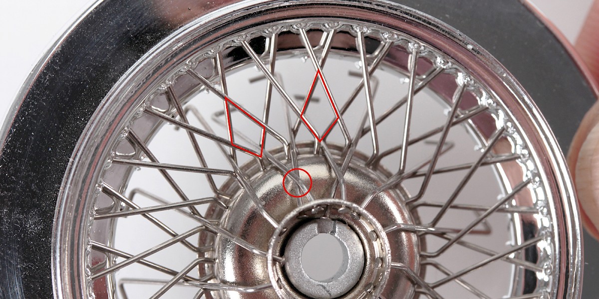
Step 5
Push another type A spoke through the next hole in the lower row. Push the end of the spoke through the diamond shape as indicated in the image.
Continue to fit type A spokes until there are 12 type A spokes in place. The ends of the type A spokes can be left loose on the opposite side.
Step 6
Push a type B spoke (40-D) through a hole in the upper row. Cross the type B spoke over the type A spoke as shown.
Step 7
Using your forefinger, press the end of the type B spoke through the diamond shape. At the same time, push the spoke through to the opposite side of the wheel.
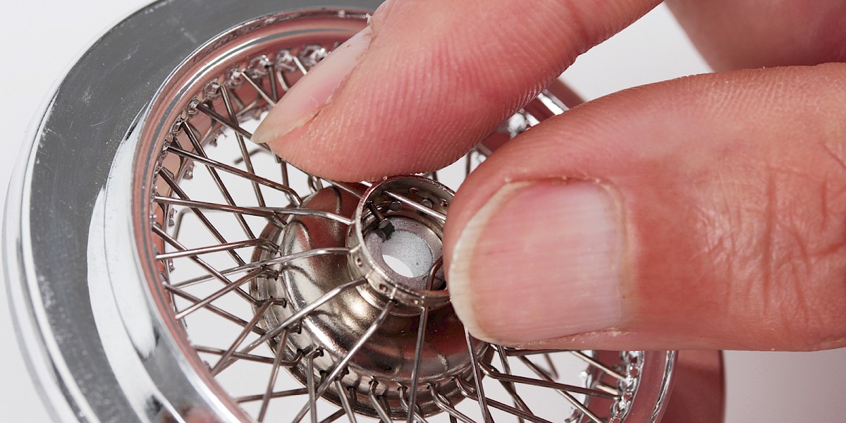
Step 8
Turn the assembly over and hook the end of the spoke over the nearest wide tooth so that the type B spoke faces one of the type A spokes.

Step 9
Push another type B spoke through the next hole in the upper row. Cross the type B spoke over the type A spoke as shown. Press the end of the type B spoke through the next diamond shape to the left.
Fit 12 type B spokes in this way.
Step 10
Place a piece of tissue paper into the wheel centre to hold the type A spokes and the type B spokes in place.
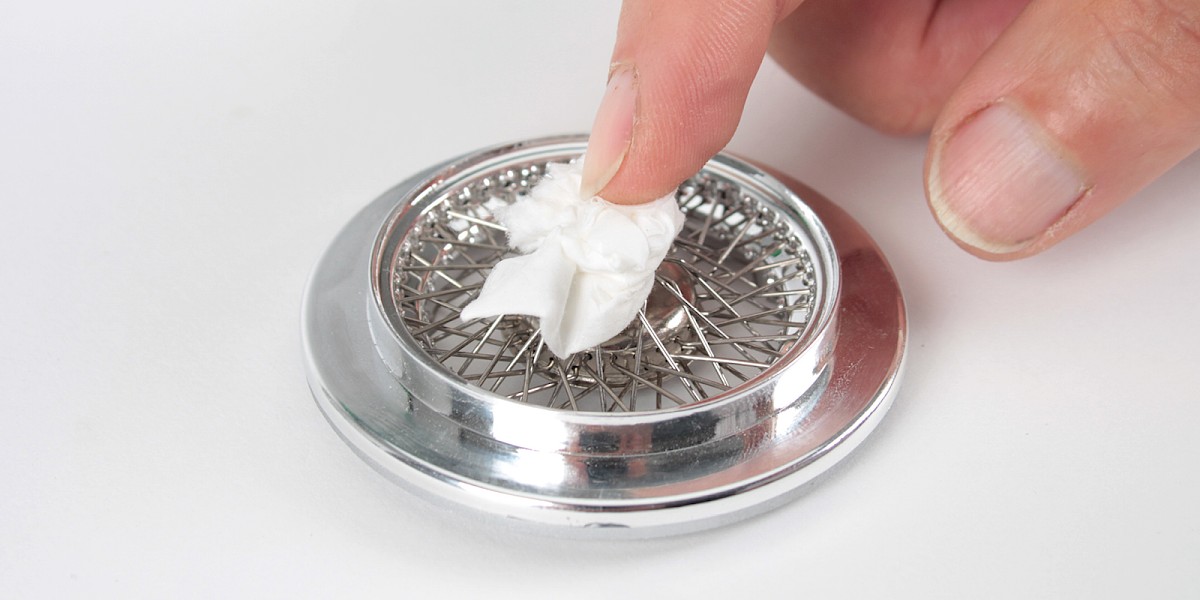
Step 11
Keep holding the tissue in place. Turn the assembly over and let the spokes fall naturally towards the teeth. Using your finger, gently hook the spokes over the wide teeth.
To adjust the tension, twist the wheel centre using the soft part of your thumb.
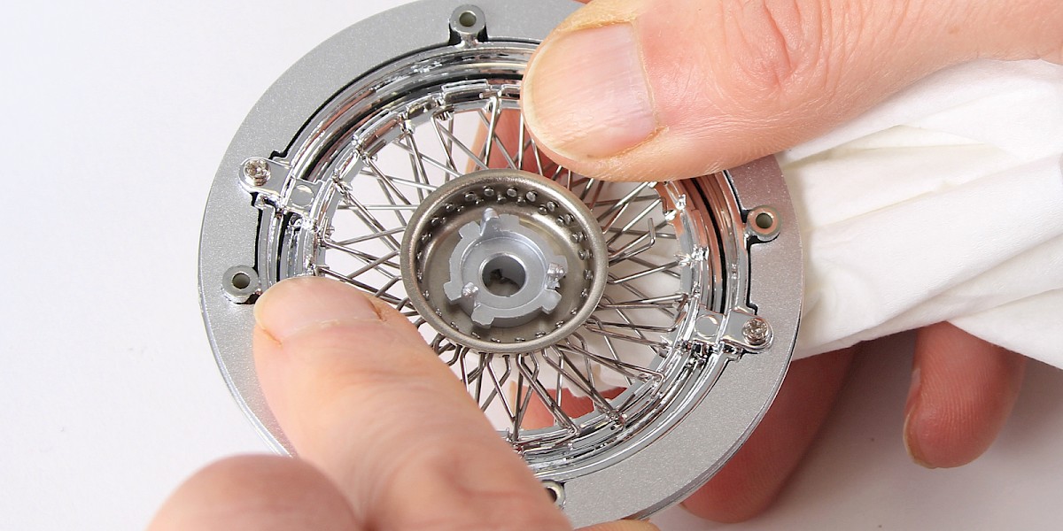
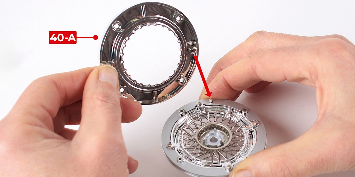
Step 12
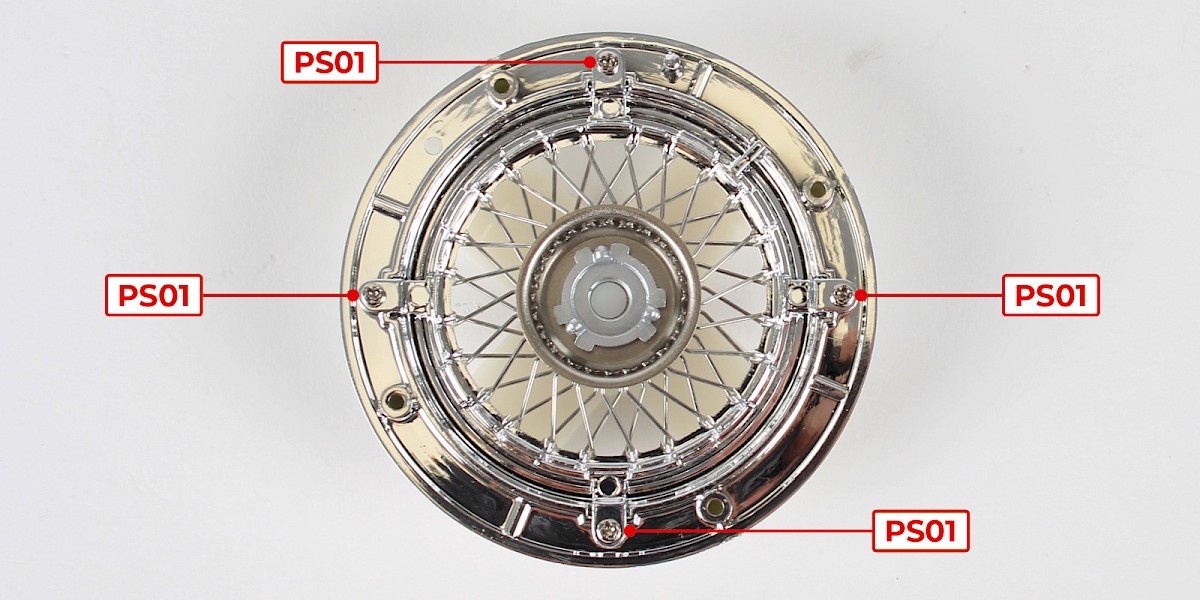
Once all the spokes are in place, fit the inner wheel rim (40-A) on top of the assembly.
Screw the parts together using 4x PS02.
STAGE COMPLETE
PARTS LIST
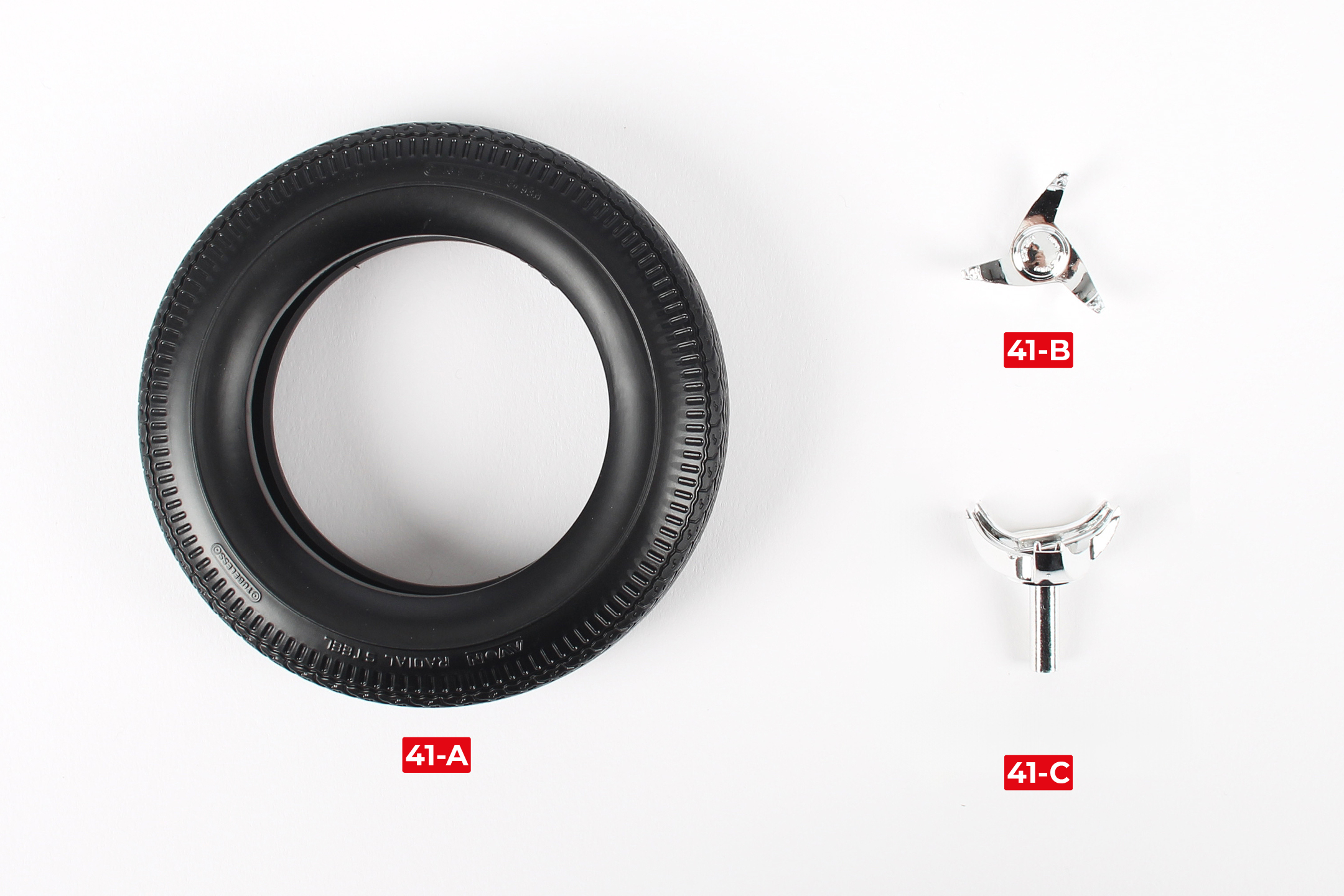
| 41-A Tyre |
| 41-B Tyre slasher |
| 41-C Hub cap* |
* The hub cap is the 'classic' tyre slasher design. In stage 100 (pack 12) you will receive a new hub cap for the slim-line tyre slasher.
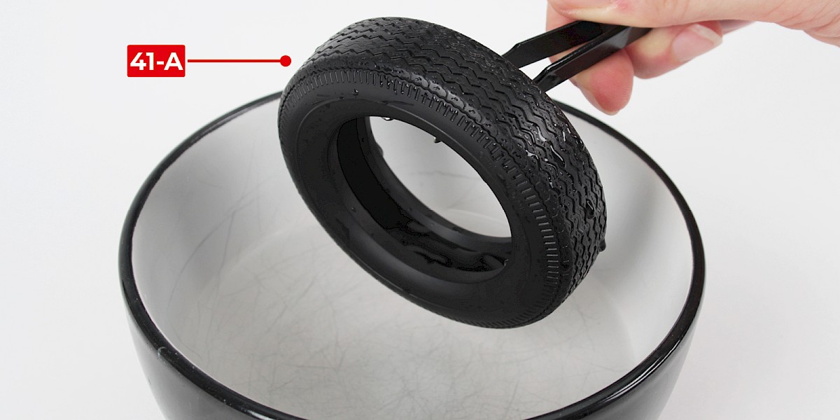
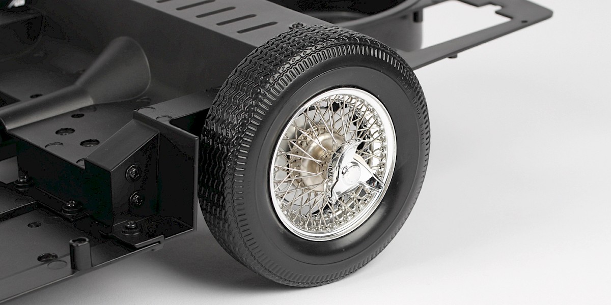
Step 1
Carefully place the tyre (41-A) in a bowl of hot water. After 1–2 minutes, use tweezers to remove the tyre. Dry the tyre with a cloth.
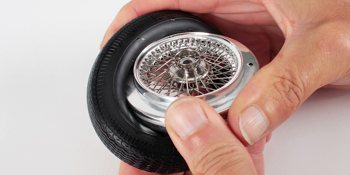
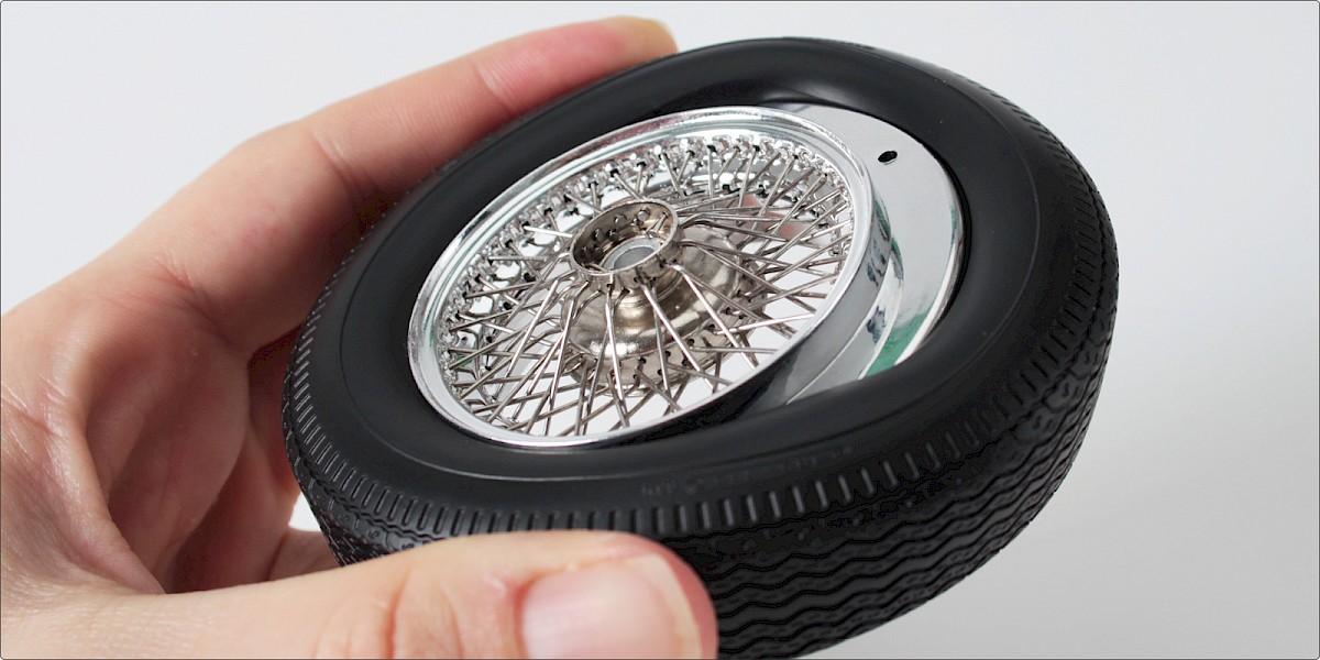
Step 2
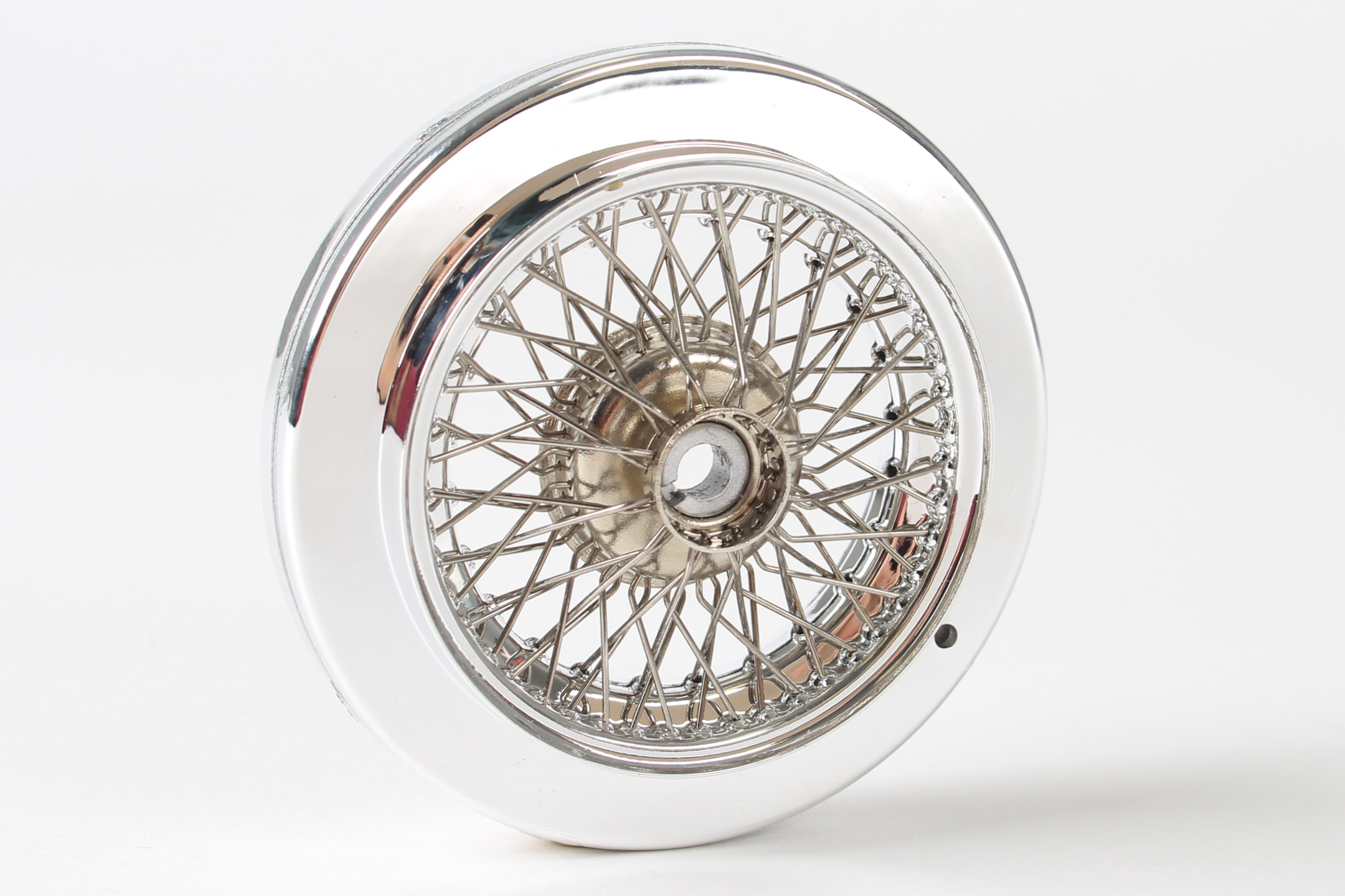
While the tyre is still flexible, fit the tyre around the wheel rim (from Stage 039VB or 040).
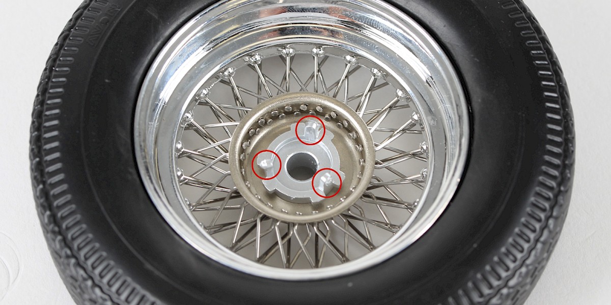
Step 3
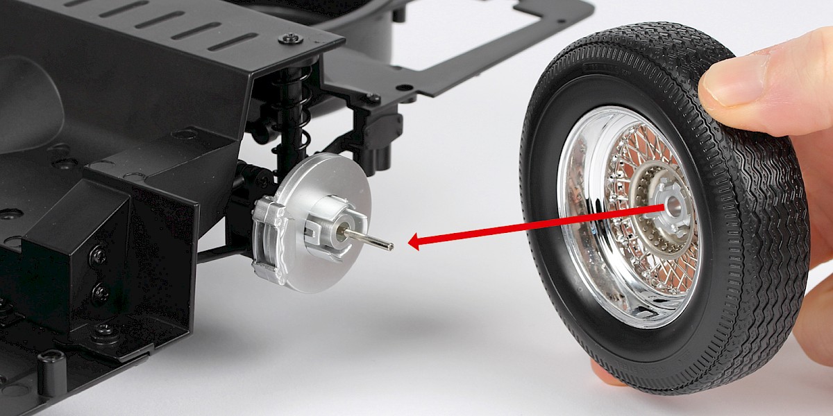
The rear wheel has three posts (a) which fit into the slots in the hub (b).
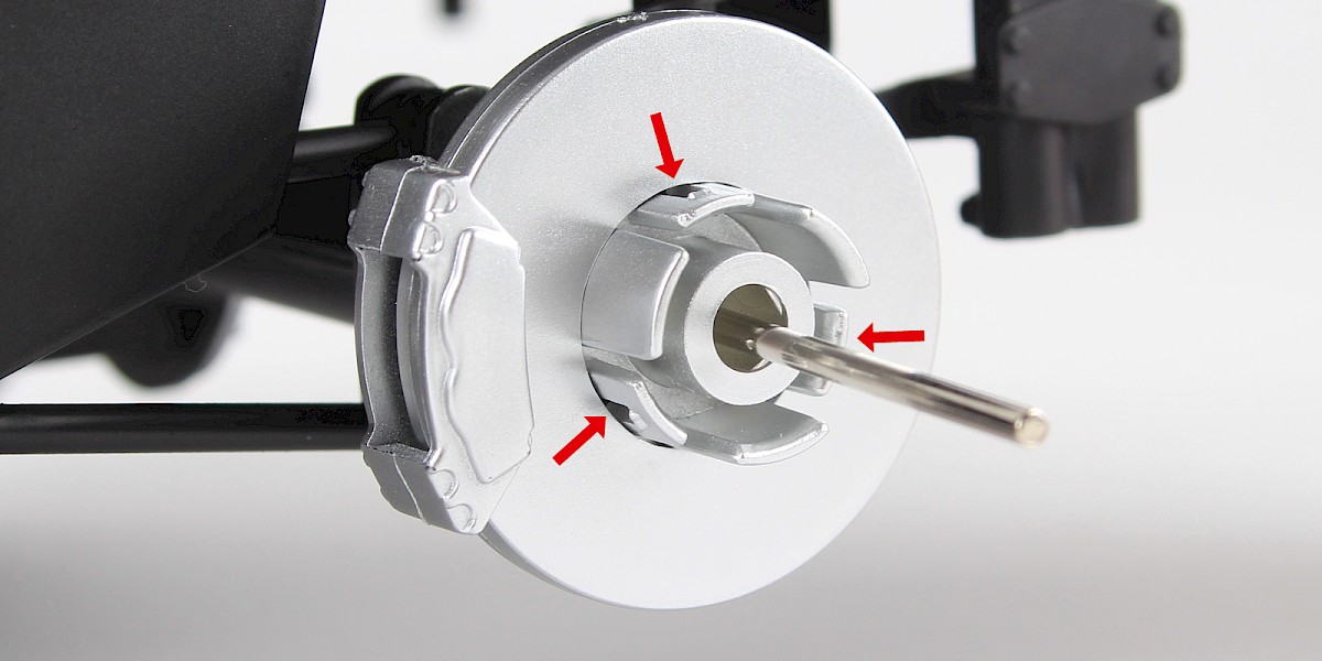
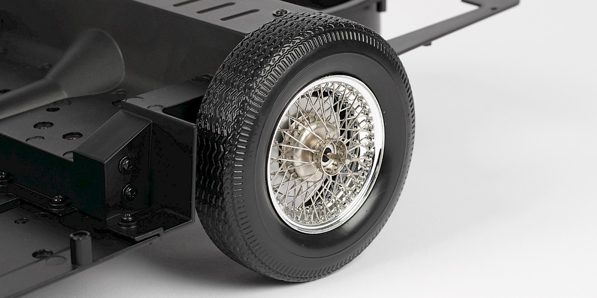
Step 4
Fit the rear wheel onto the hub.
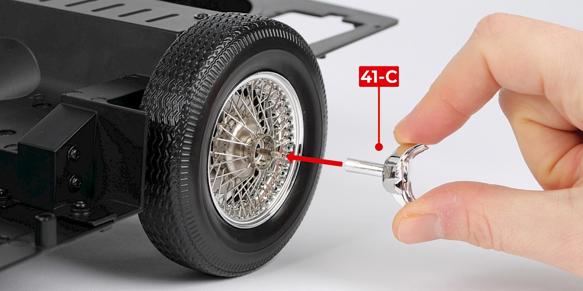
Step 5
Fit the hub cap (41-C) over the pin in the centre of the wheel.
Press the tyre slasher (41-B) onto the pin.
Do not glue any of these parts.
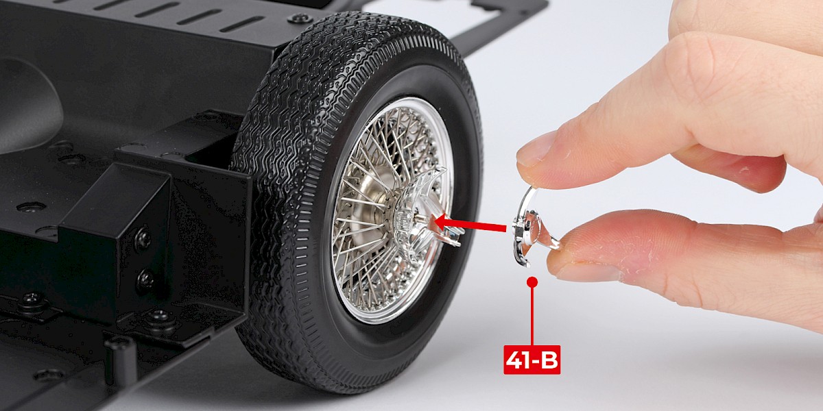
Step 6
Pull gently to extend the tyre slasher.

STAGE COMPLETE
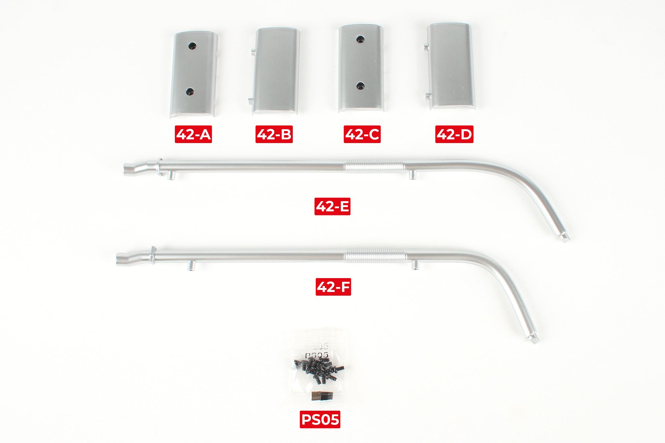
PARTS LIST
| 42-A Muffler part A | 42-E Exhaust pipe |
| 42-B Muffler part B | 42-F Exhaust pipe |
| 42-C Muffler part C | 13x PS05 screws |
| 42-D Muffler part D |
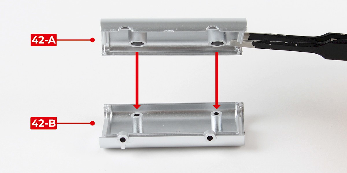
Step 1
Fit muffler part A (42-A) to muffler part B (42-B).
Secure using 2x PS05.
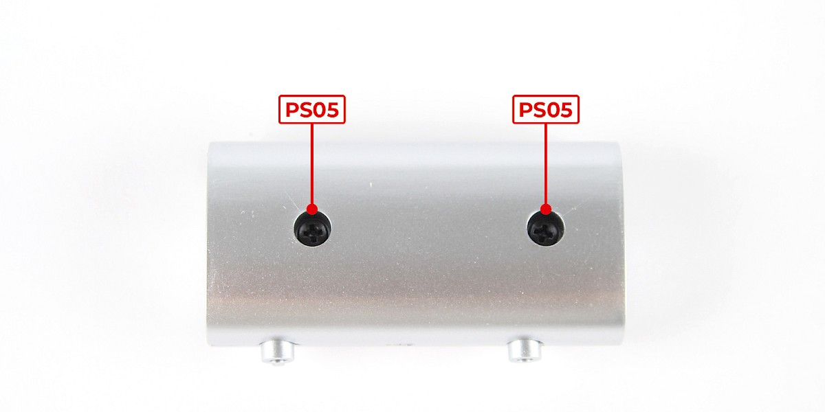
Step 2
Fit muffler part C (42-C) to muffler part D (42-D).
Secure with 2x PS05.
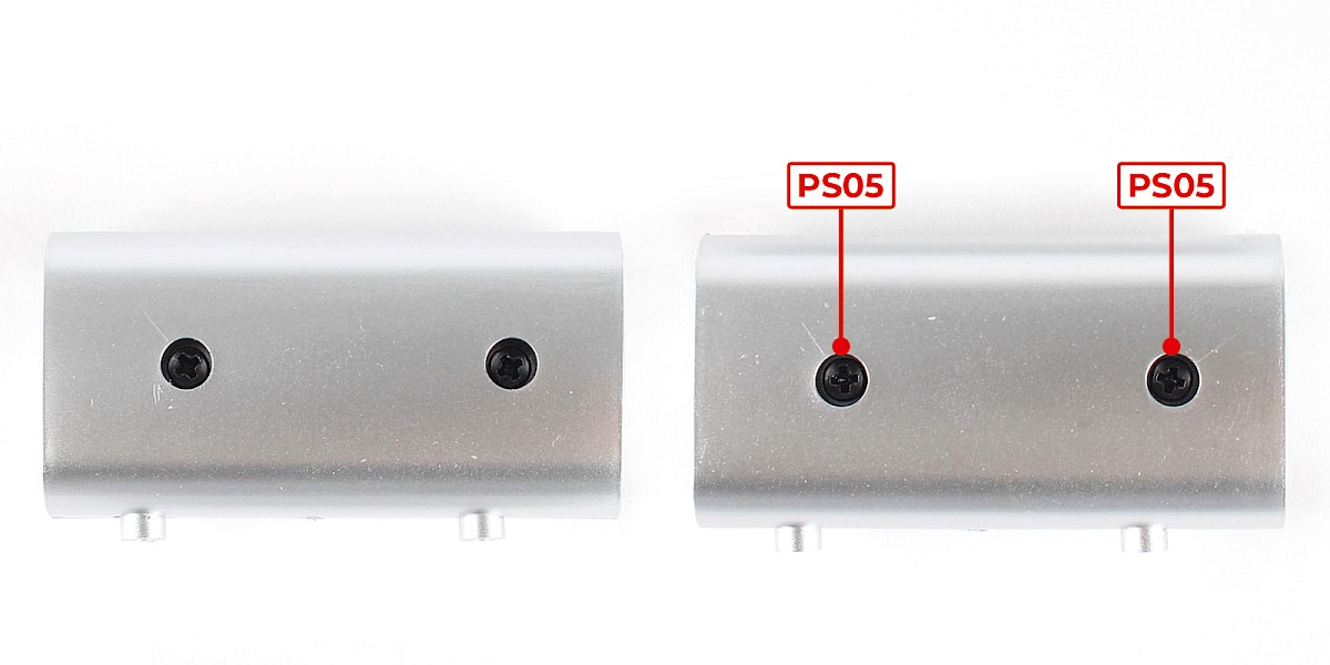
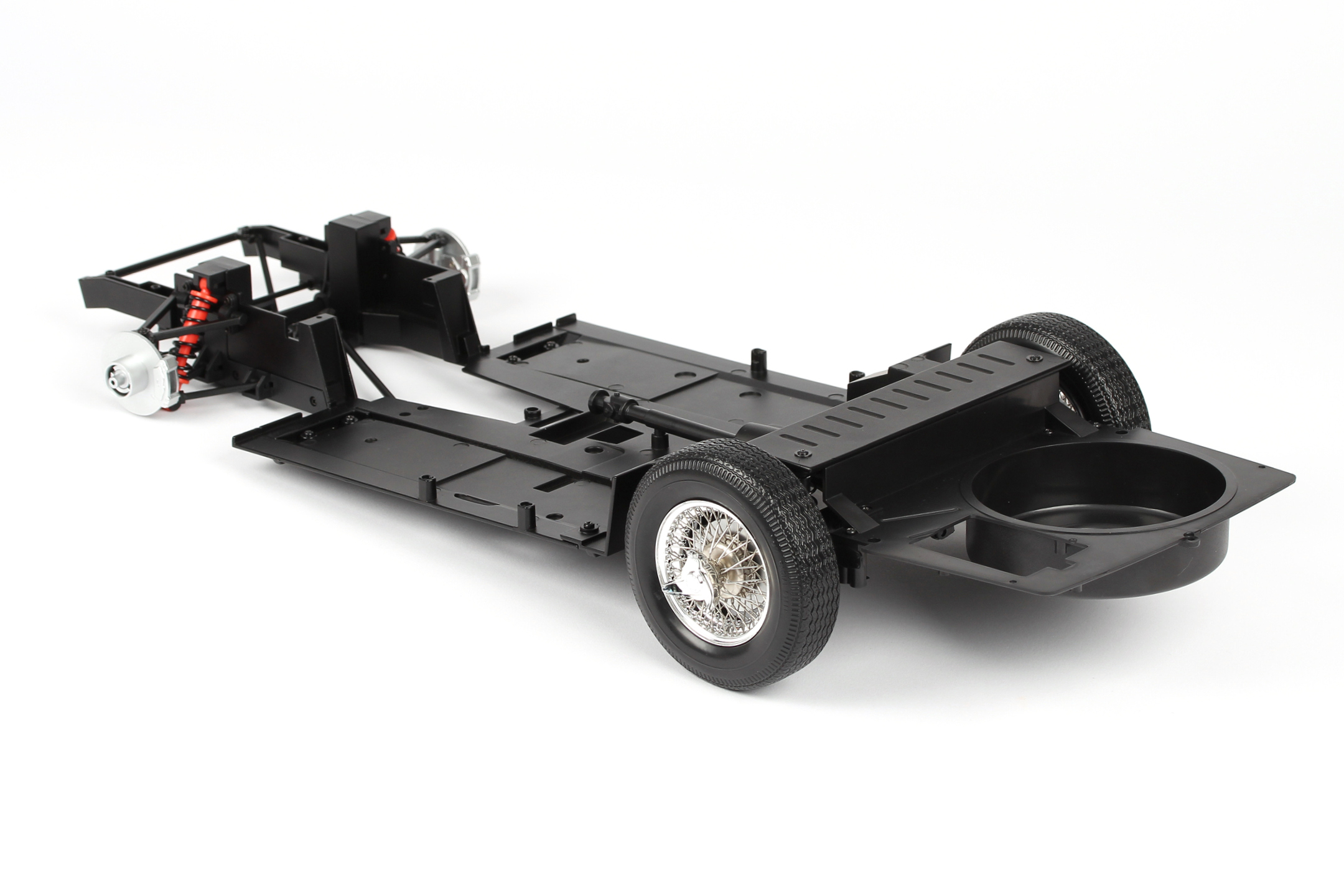
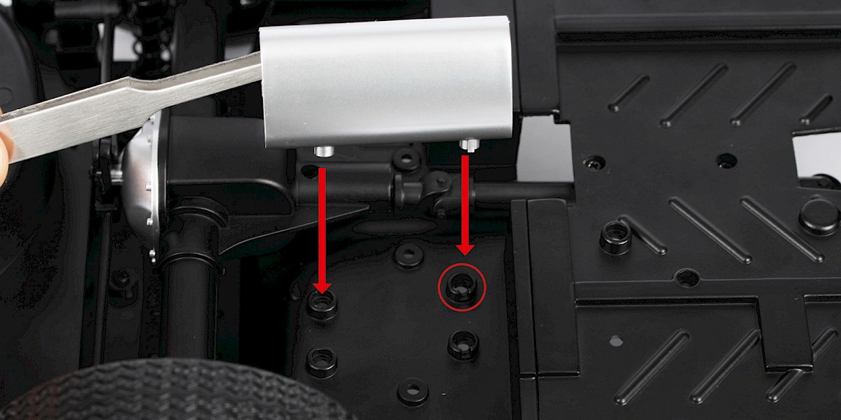
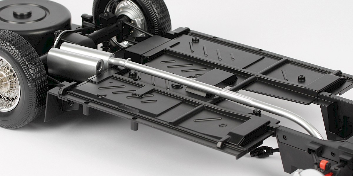
Step 3
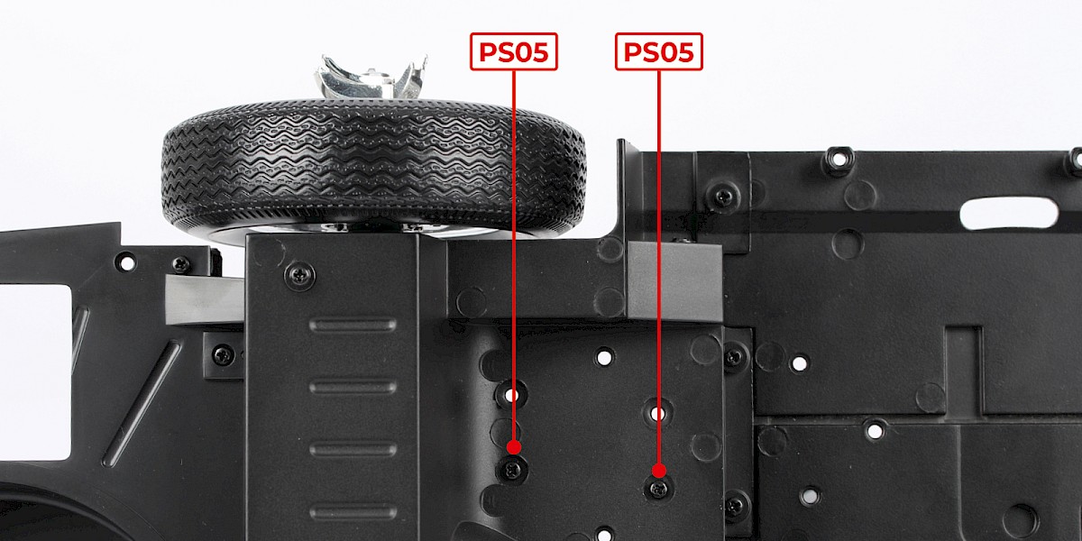
Fit a muffler onto the underside of the chassis assembly.
Step 4
Secure from the other side with 2x PS05.
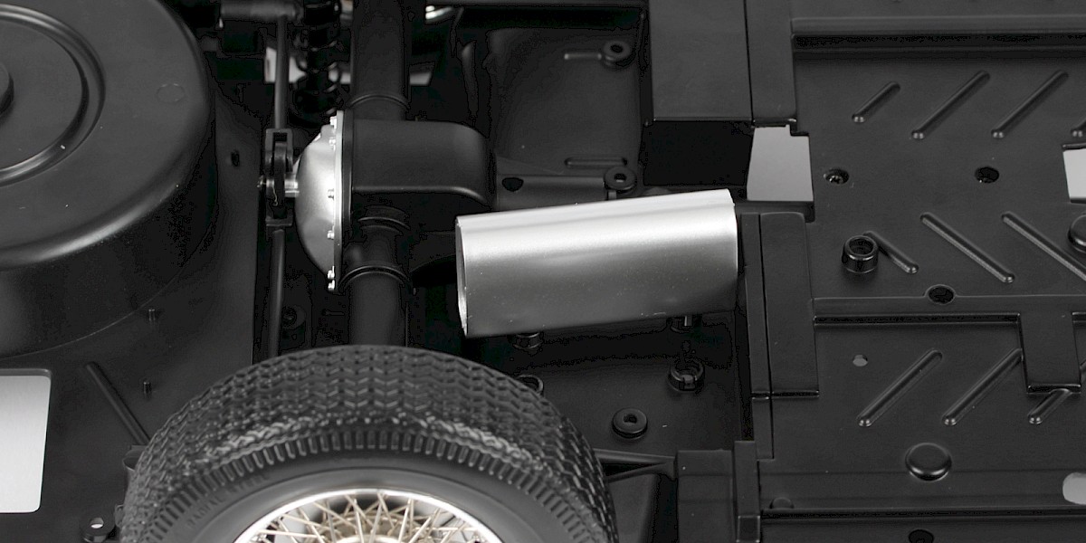
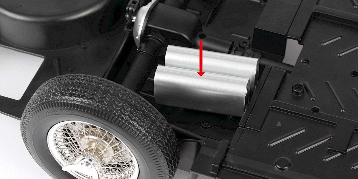
Step 5
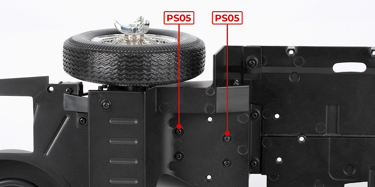
Fit another muffler onto the underside of the chassis assembly.
Secure from the other side with 2x PS05.
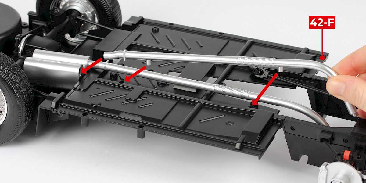
Step 6
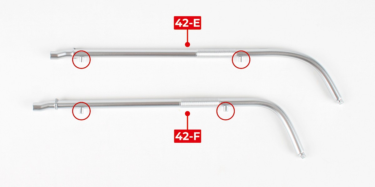
Place the two exhaust pipes (42-E and 42-F) as shown. Note: the screw posts are further apart on 42-E.
Step 7
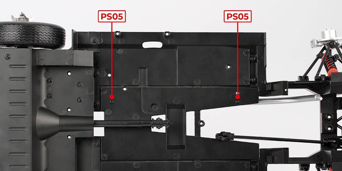
Fit the right exhaust pipe (42-E) to the muffler and the chassis.

Step 8
Secure from the other side with 2x PS05.
Step 9
Fit the left exhaust pipe (42-F) to the muffler and the chassis.
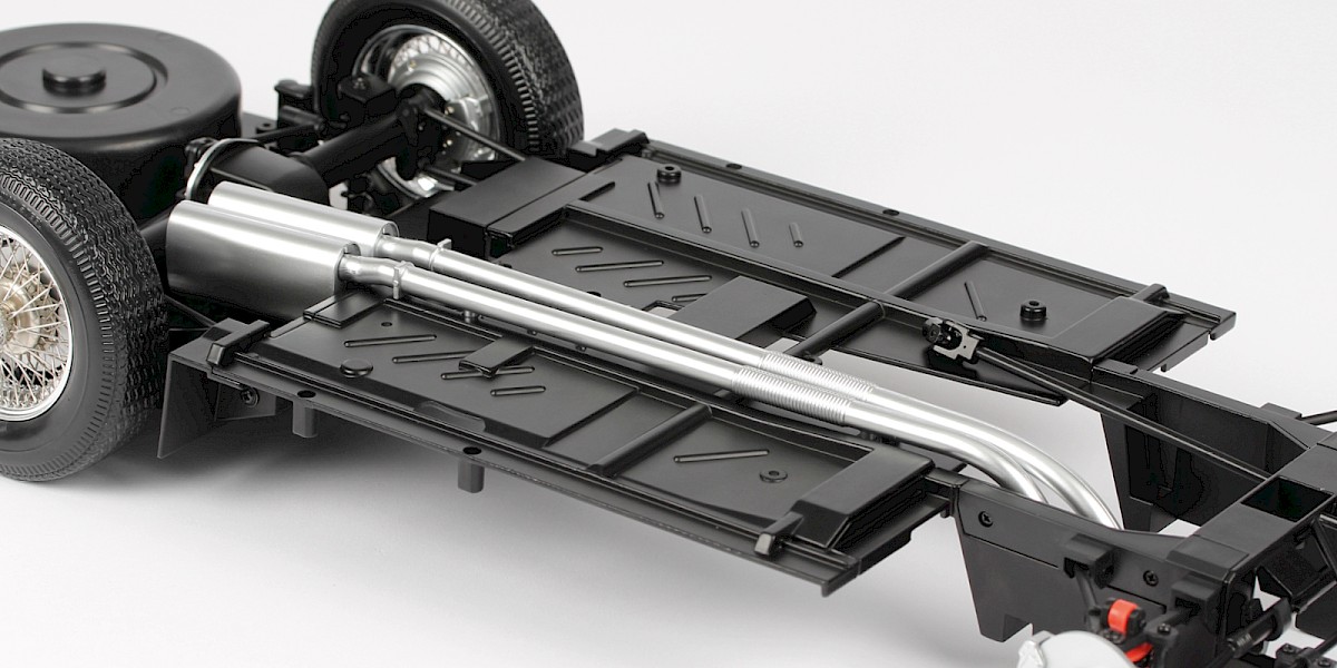
Step 10
Secure from the other side with 2x PS05.
STAGE COMPLETE
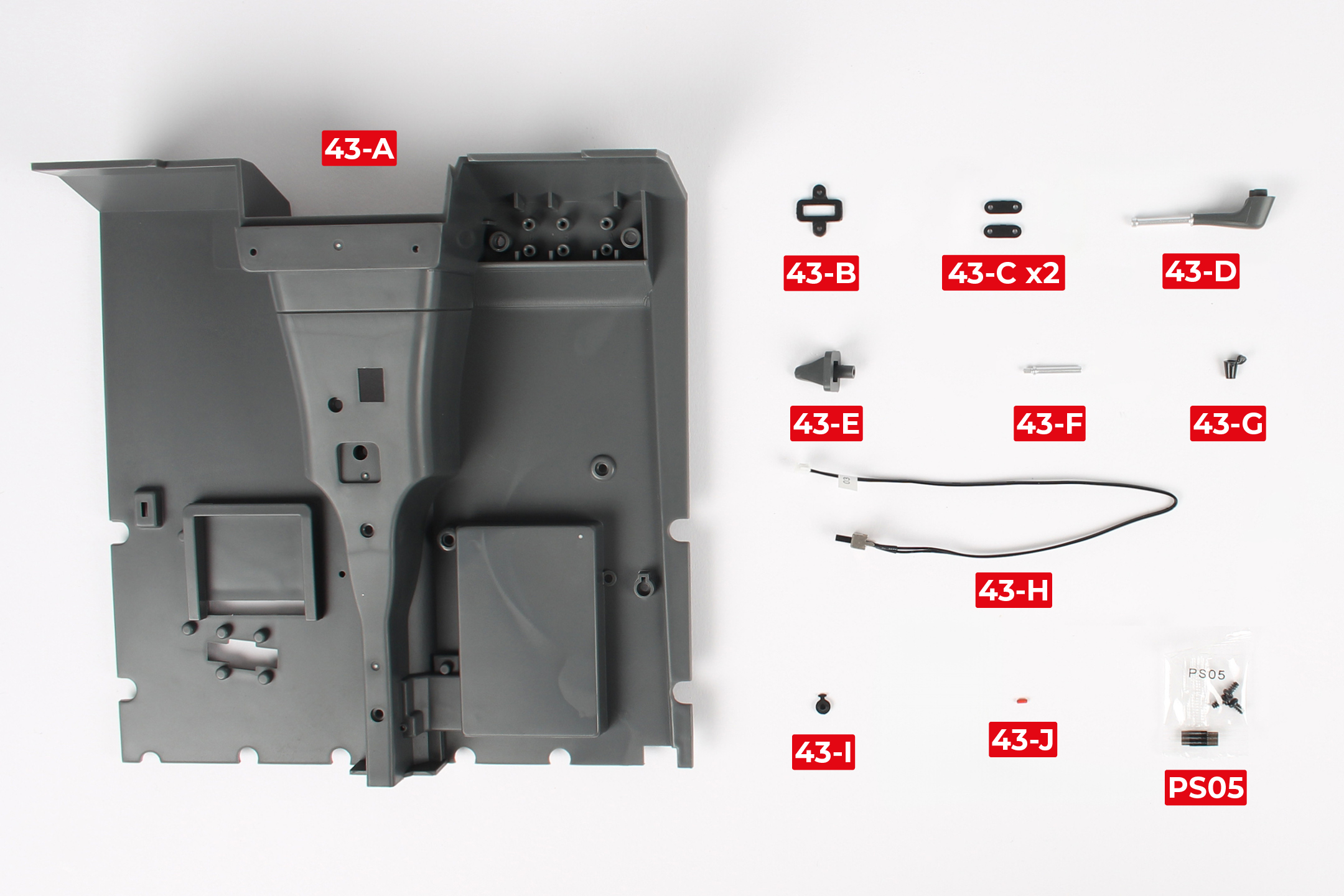
PARTS LIST
| 43-A Cockpit floor | 43-F Gear stick | 3x PS05 screw |
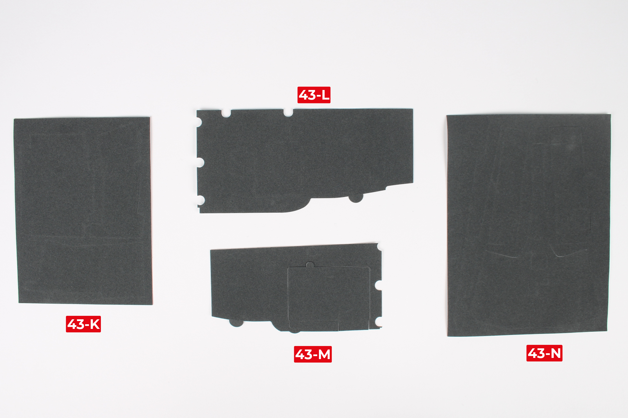
| 43-B Power-switch bracket | 43-G Gear-stick knob | 43-K Carpet part 1 |
| 43-C Wire bracket x2 | 43-H Power switch | 43-L Carpet part 2 |
| 43-D Handbrake | 43-I Gear stick knob lid | 43-M Carpet part 3 |
| 43-E Gear stick boot | 43-J Ejector-seat button | 43-N Carpet part 4 |
Step 1
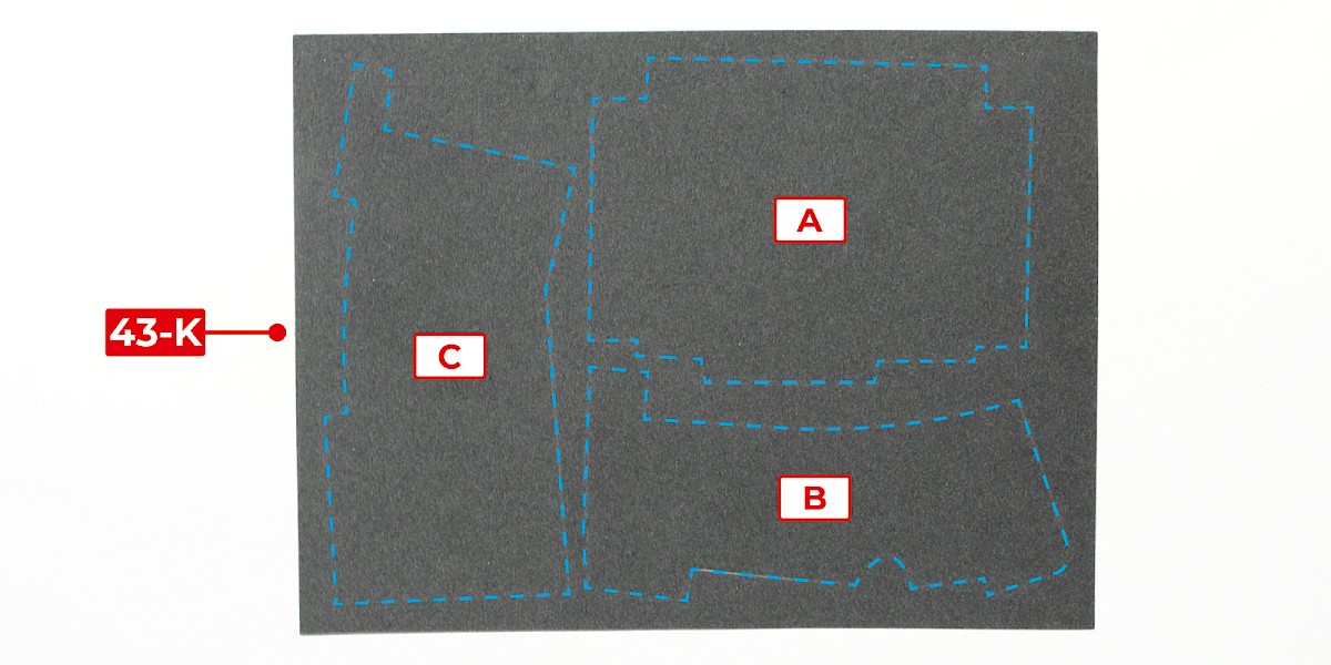
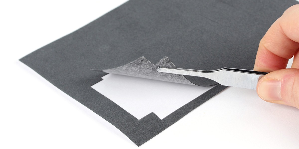
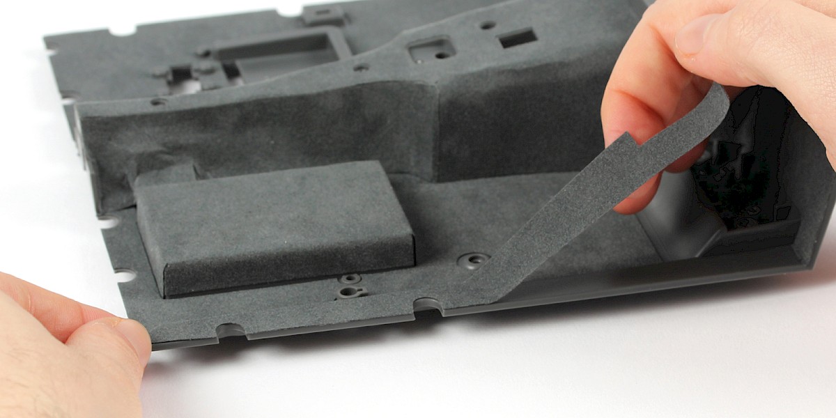
Take carpet part 1 (43-K). Note the three carpet pieces (A, B and C).
Remove carpet piece A.
Step 2
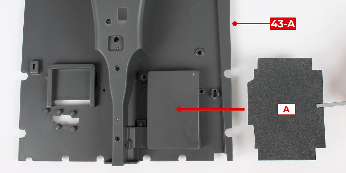
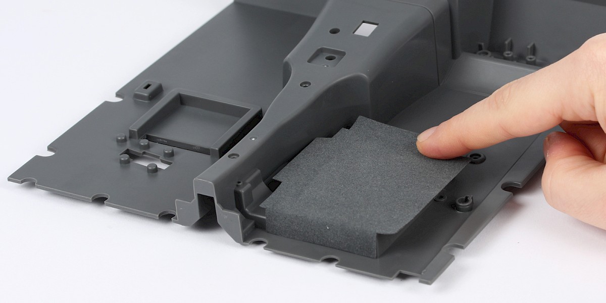
Carpet piece A will be stuck to the cockpit floor (43-A) as shown.
Step 3
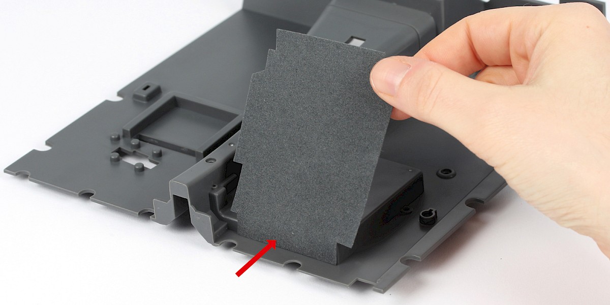
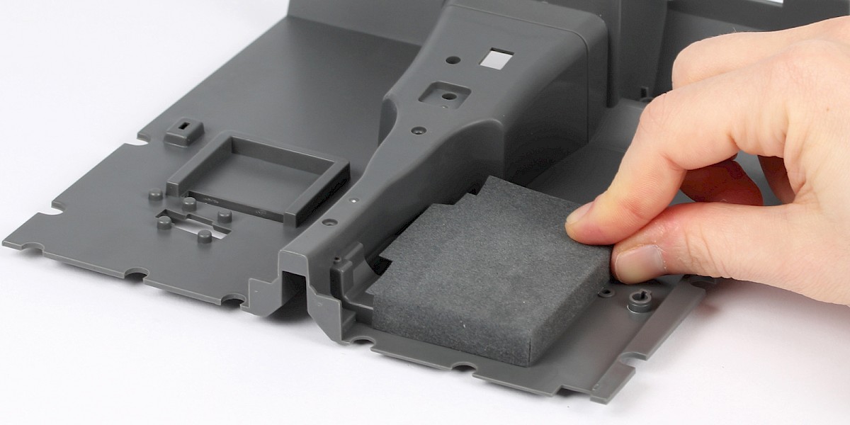
Place carpet piece A onto the cockpit floor as shown.
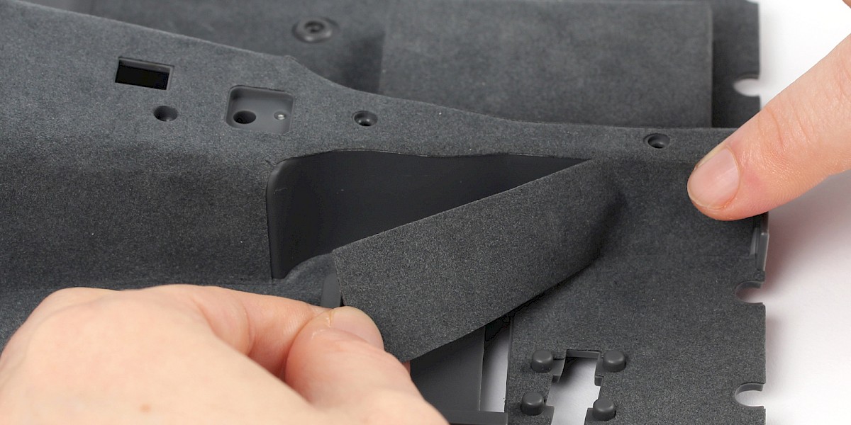
Step 4
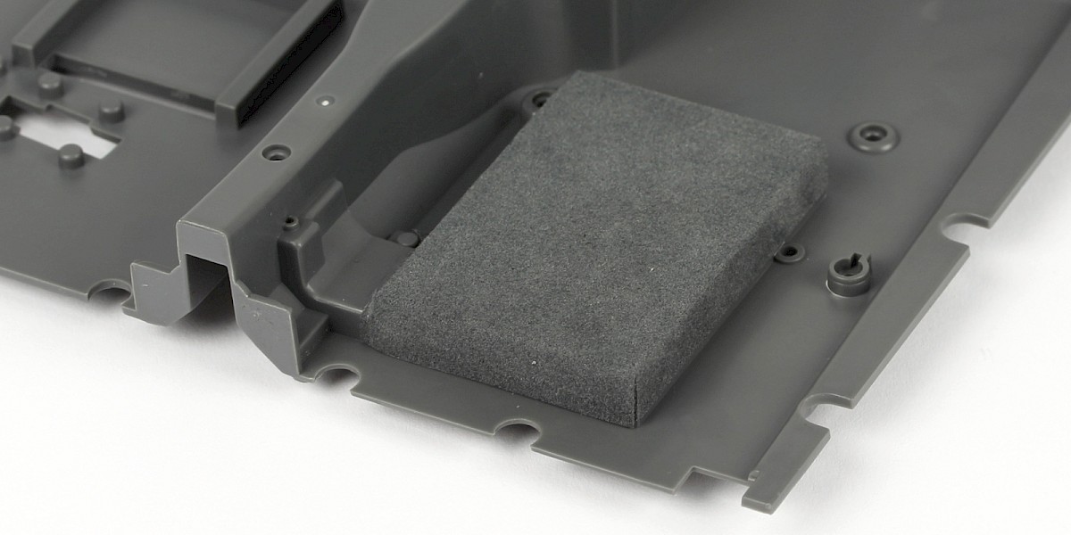
Press the edges of carpet piece A into place.
Step 5
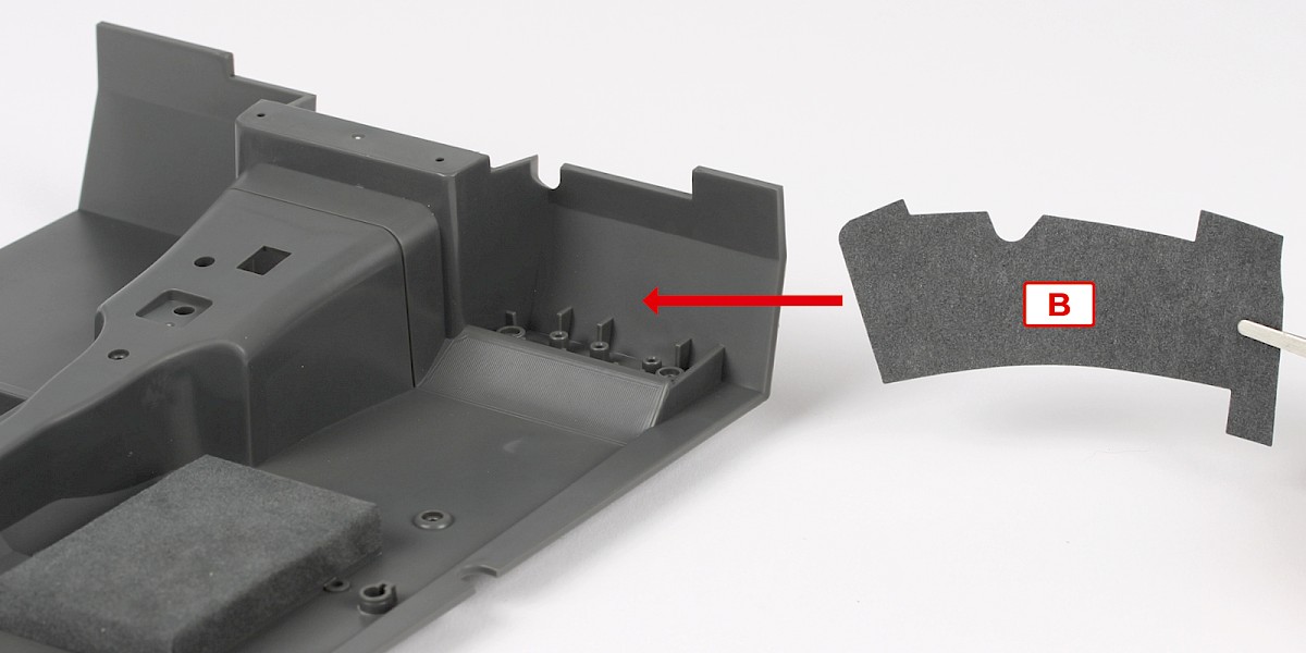
Carpet piece B will be stuck to the cockpit floor as shown.
Step 6
Place carpet piece B as shown.
Step 7
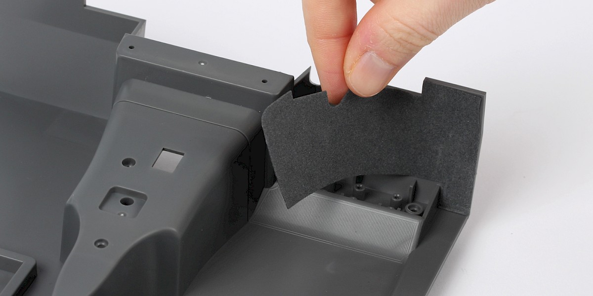
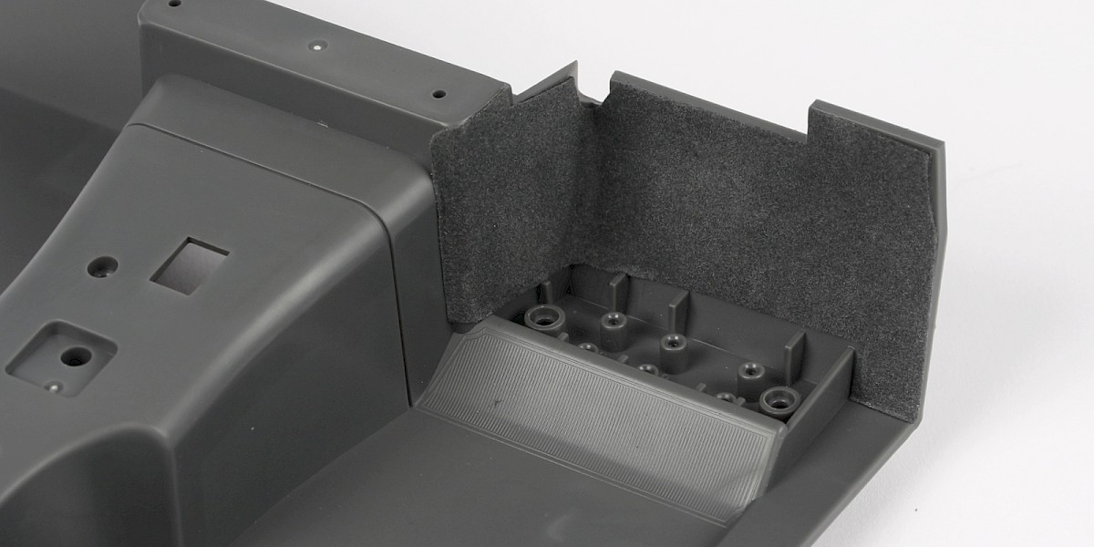
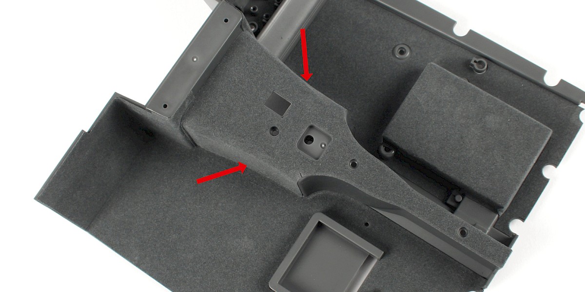
Carpet piece C will be stuck to the cockpit floor as shown.
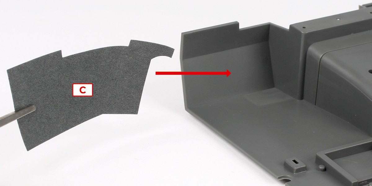
Step 8
Place carpet piece C as shown.
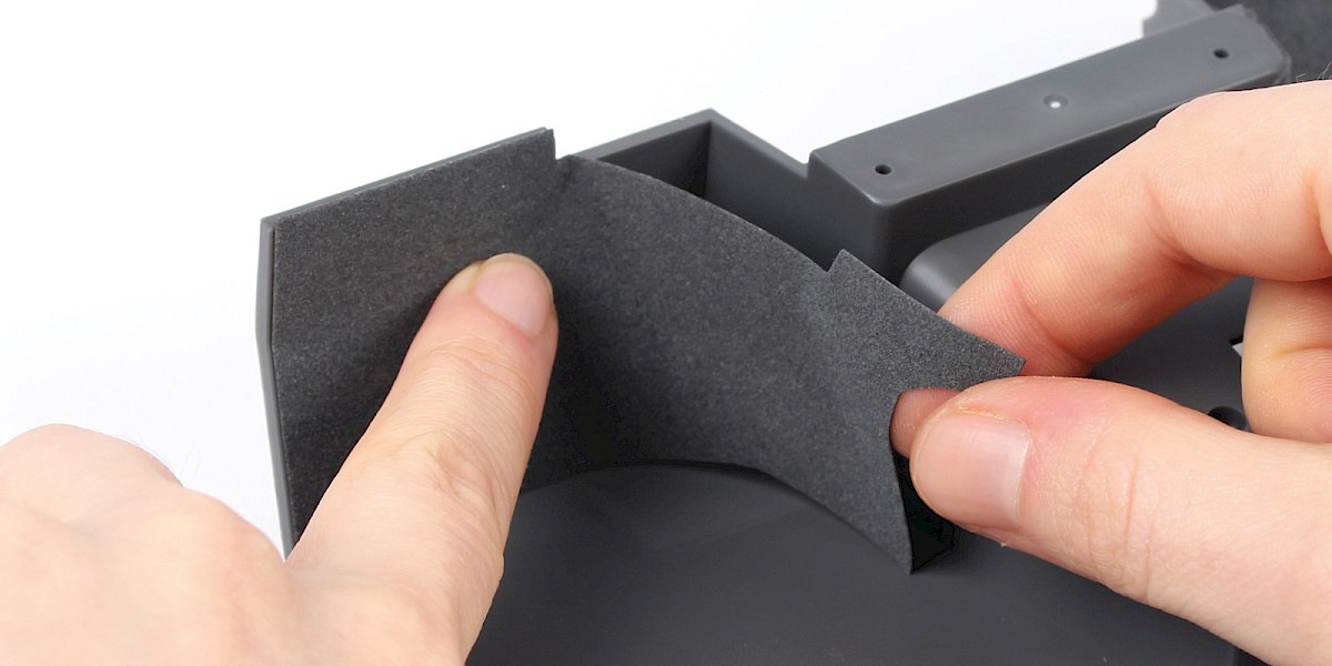
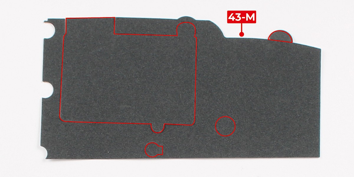
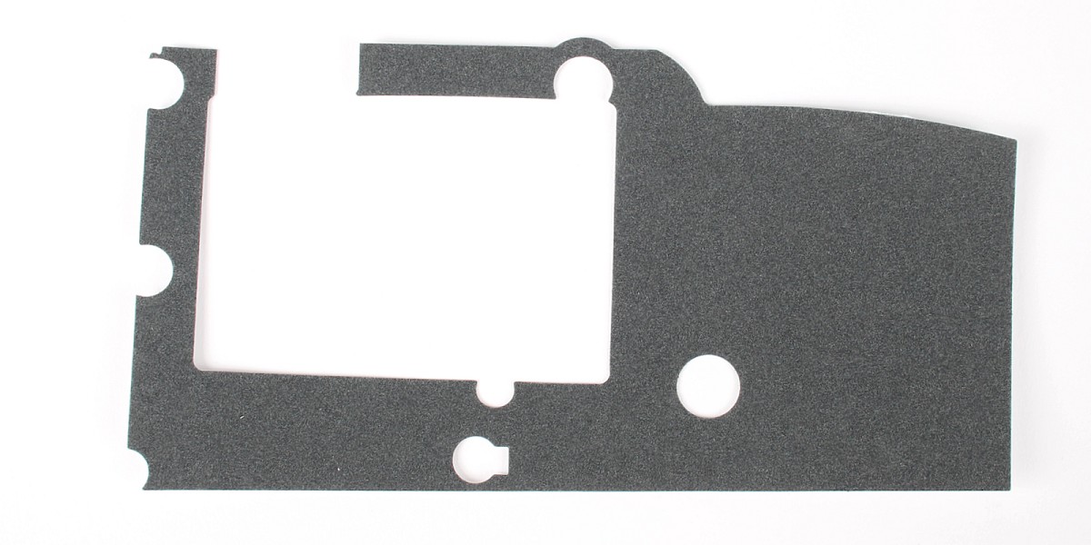
Step 9
Take carpet part 3 (43-M) and detach the pieces following the red outline.
Step 10
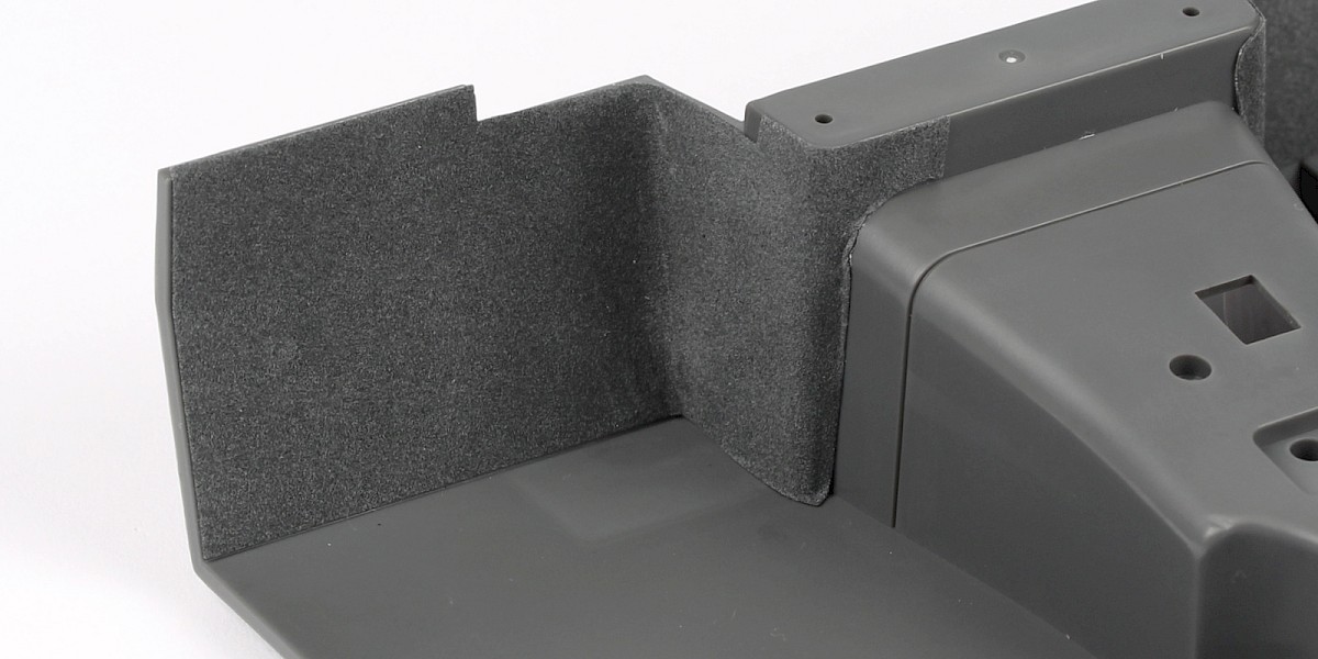
Carpet part 3 will be stuck to the cockpit floor as shown.
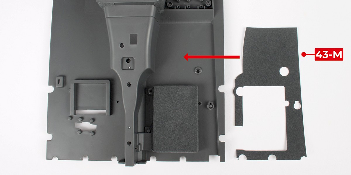
Step 11
Place carpet part 3 as shown.
Step 12
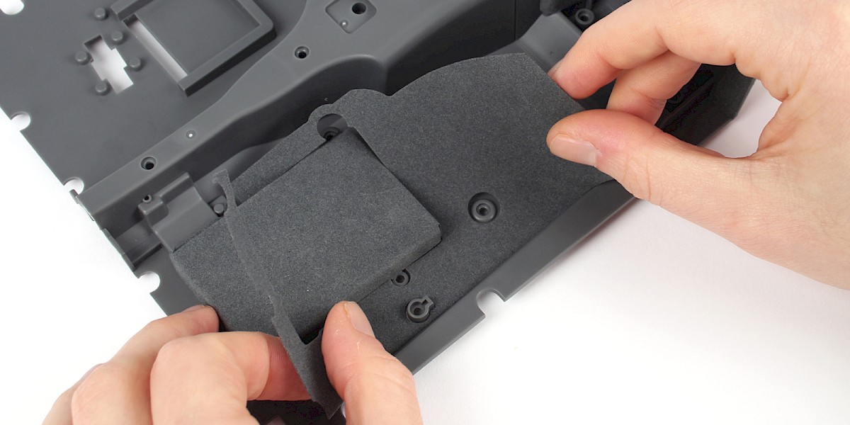
Take carpet part 2 (43-L) and detach the pieces following the red outline.
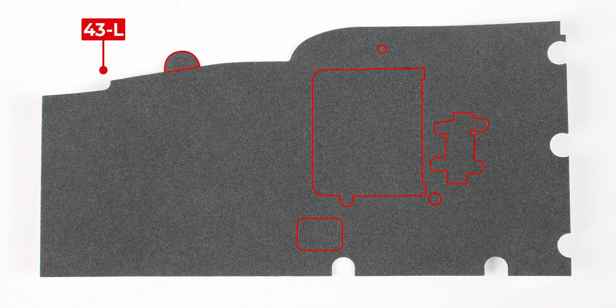
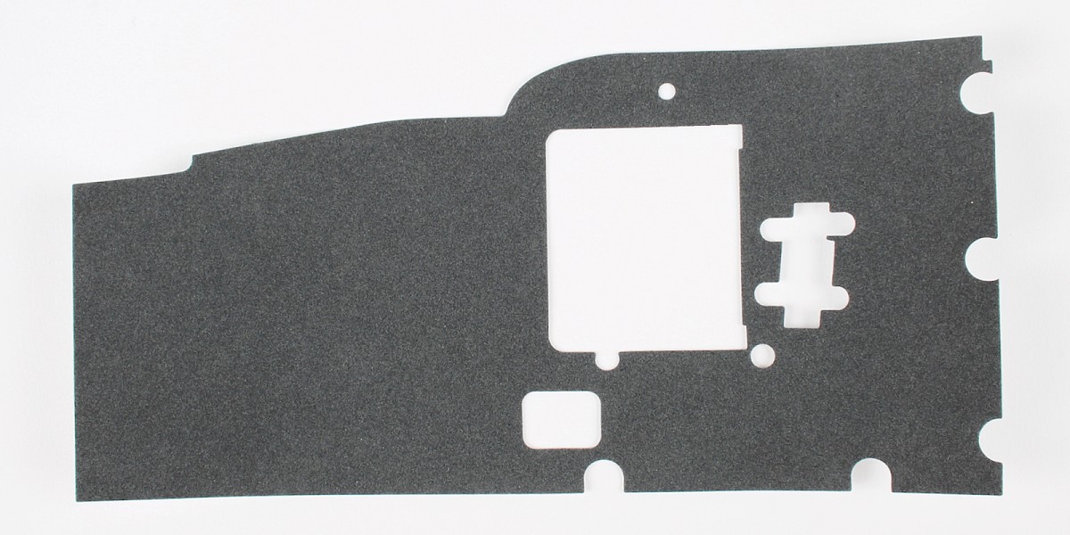
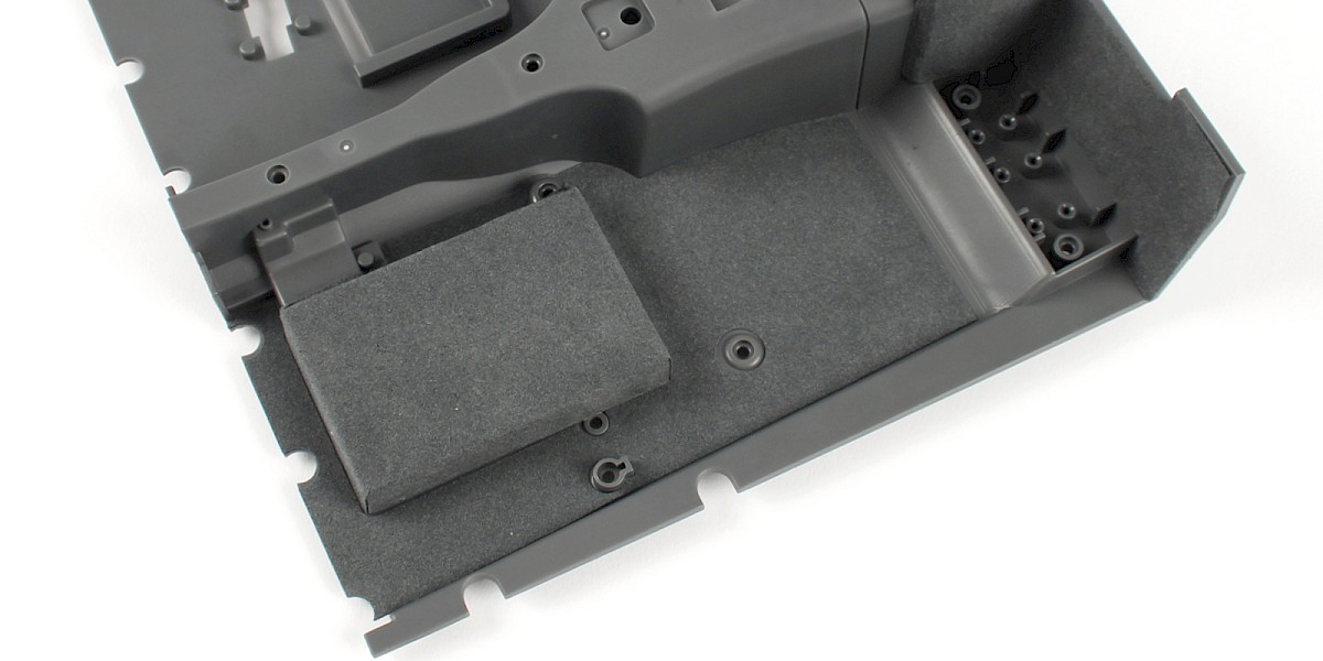
Step 13
Place carpet part 2 onto the cockpit floor as shown.

Step 14
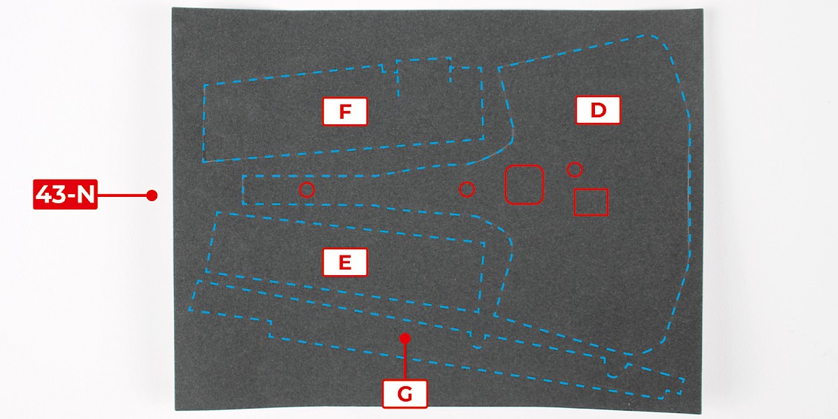
Take carpet part 4 (43-N). Note the four pieces (D, E, F and G).
Detach the pieces following the red outline.
Step 15
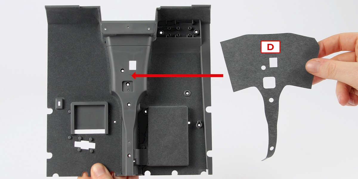
Carpet piece D will be stuck to the cockpit floor as shown.
Step 16
Place carpet piece D onto the cockpit floor.
Step 17
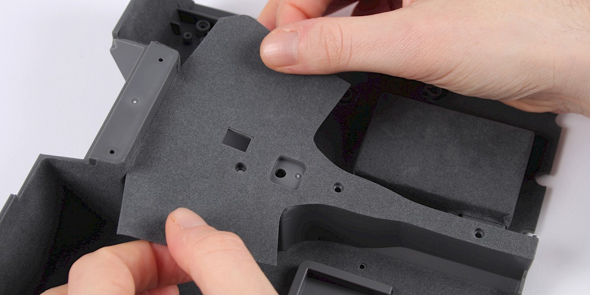
Take carpet piece E.
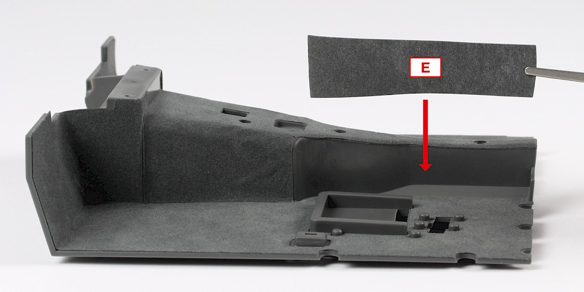
Step 18
Place carpet piece E as shown.
Step 19
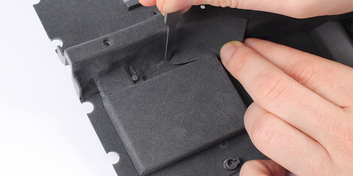
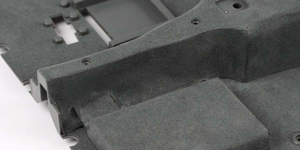
Take carpet piece F.
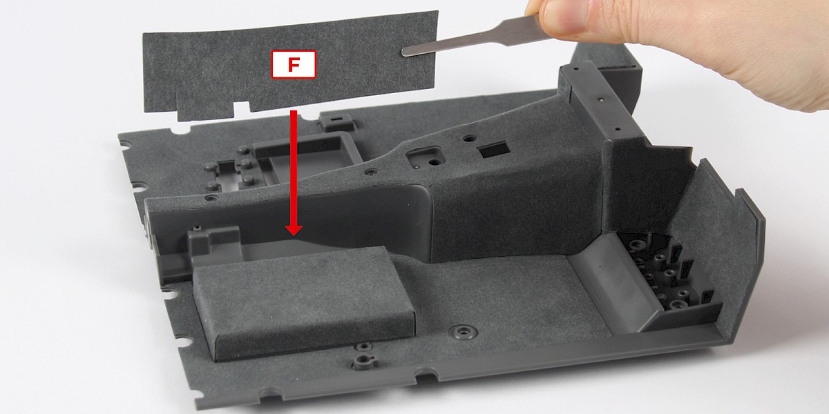
Step 20
Place carpet piece F as shown.
Step 21
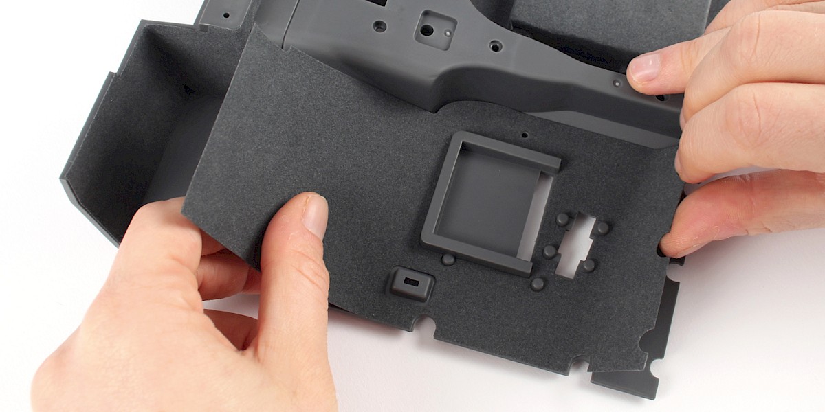
Take carpet piece G. Place carpet piece G along the outer edge of the cockpit floor as shown.
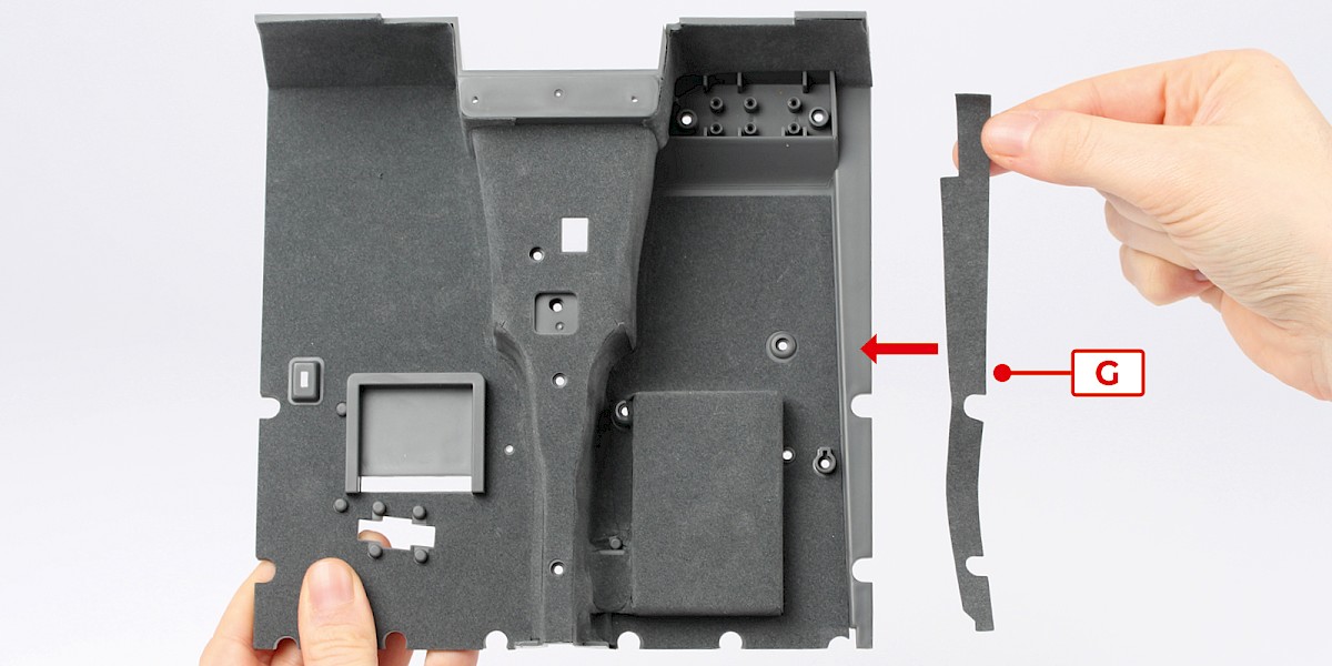
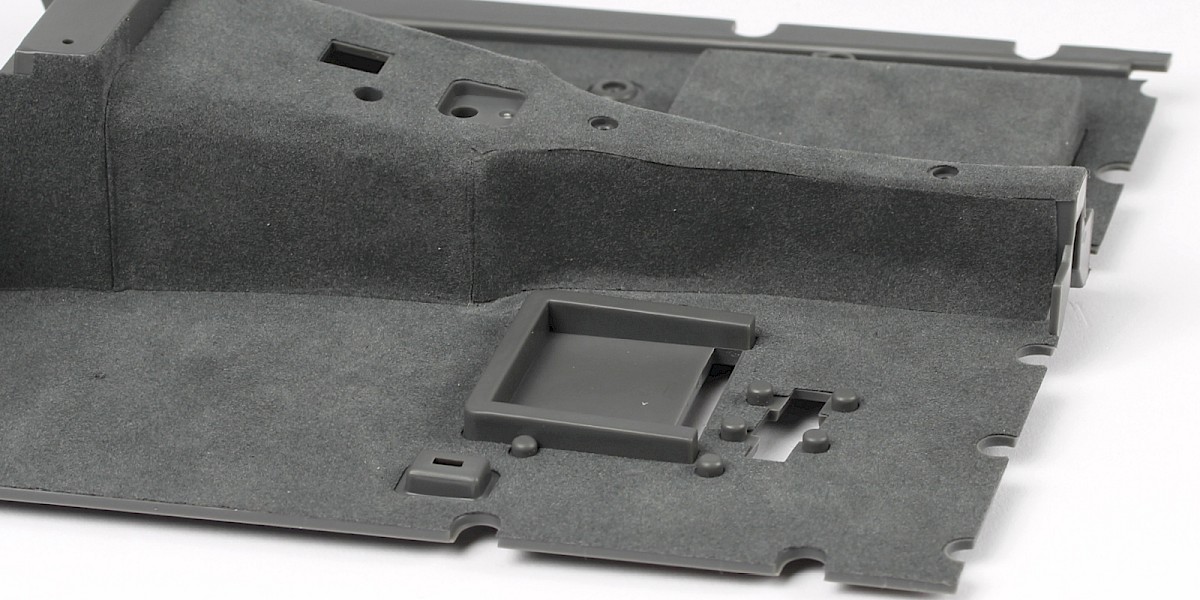
Step 22
Press the edges of carpet piece G into place.
Step 23
Any gaps in the carpet can be filled with left-over pieces.
Step 24
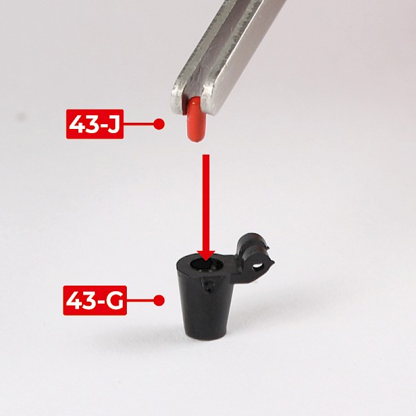
You will now build the gear stick.
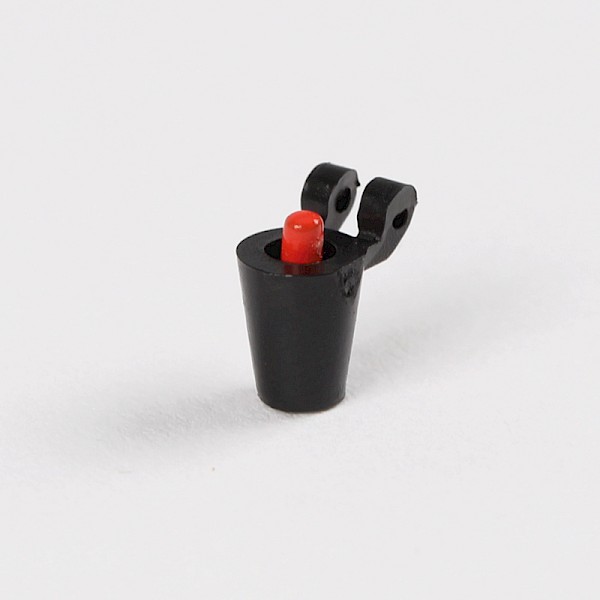
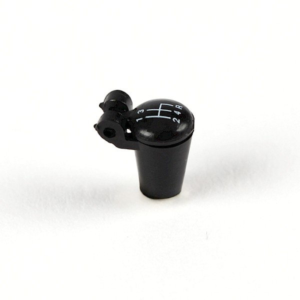
Fit the ejector-seat button (43-J) into the gear-stick knob (43-G).
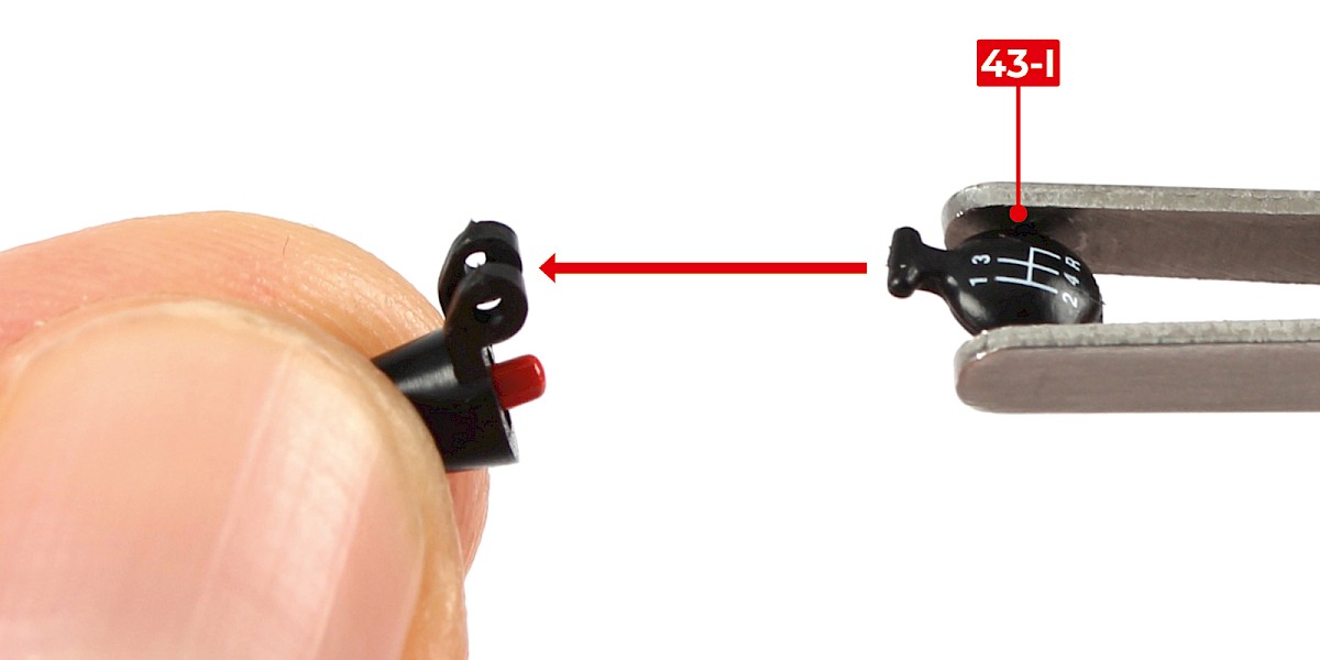
Step 25
Fit the gear-stick knob lid (43-I) to the gear stick knob.
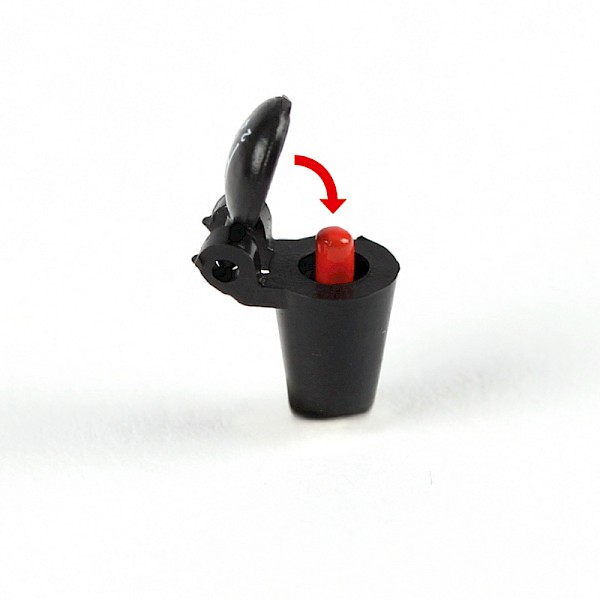
Step 26
Check the gear-stick knob lid is able to close.
Step 27
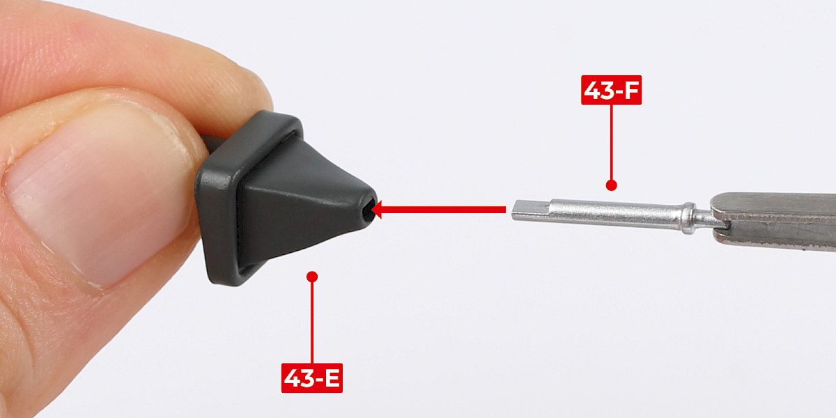
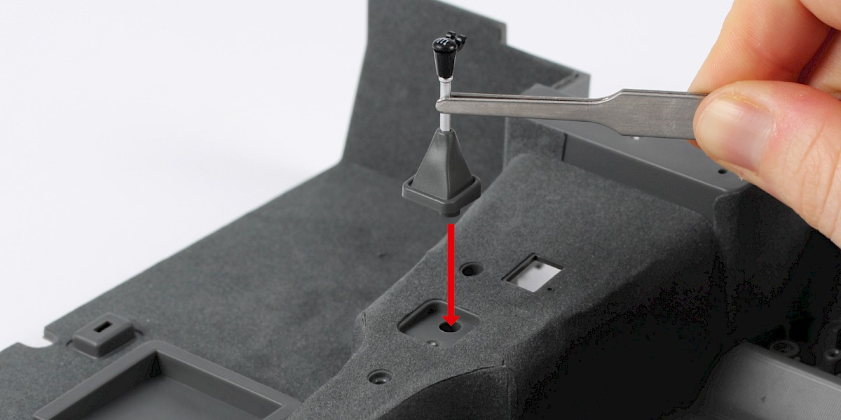
Fit the gear stick (43-F) to the gear stick boot (43-E).
Step 28
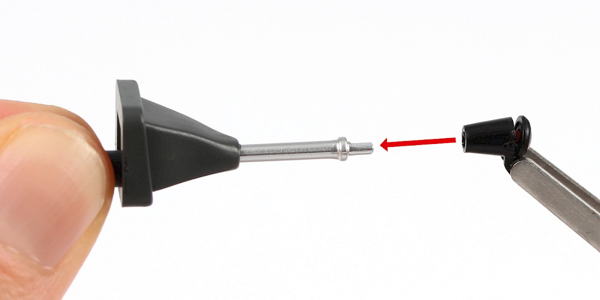
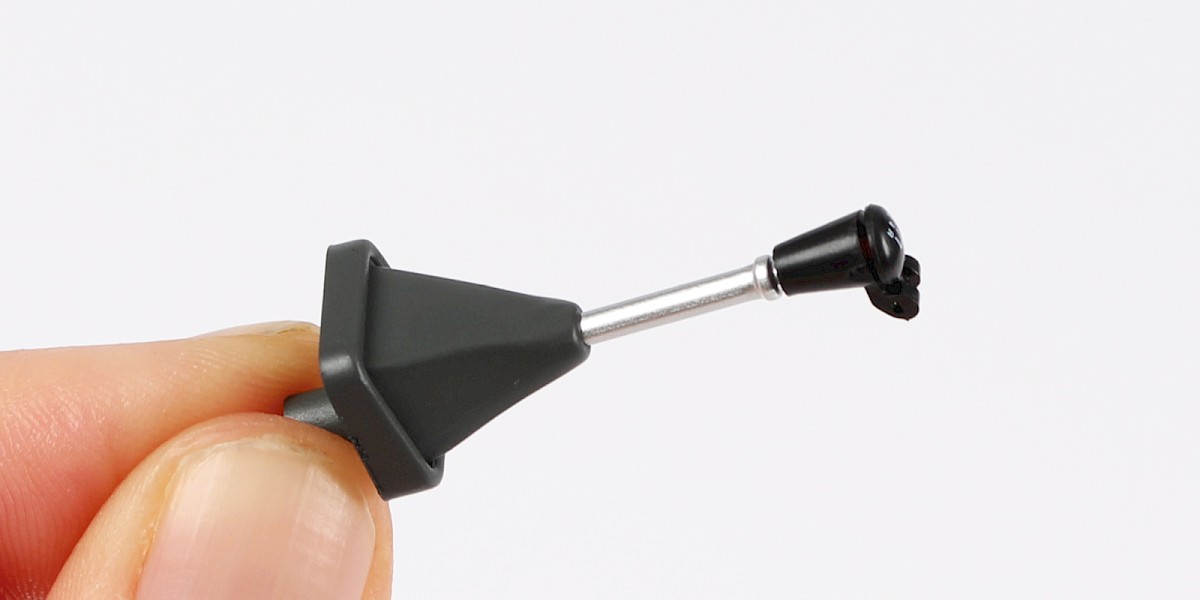
Fit the gear stick knob to the gear stick.
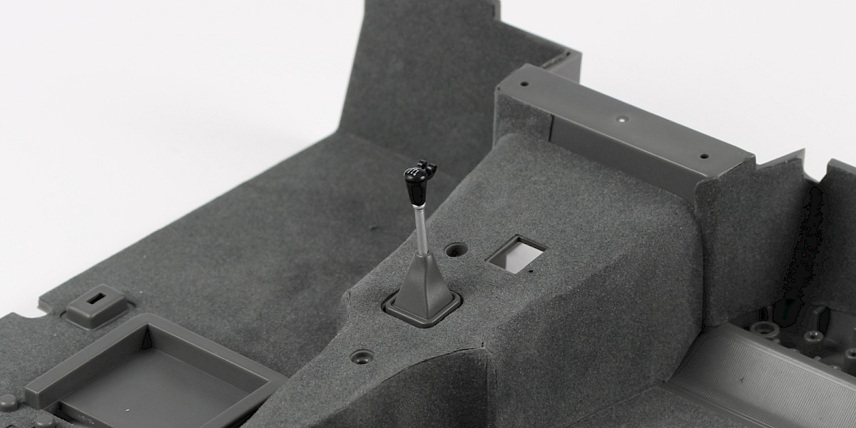
Step 29
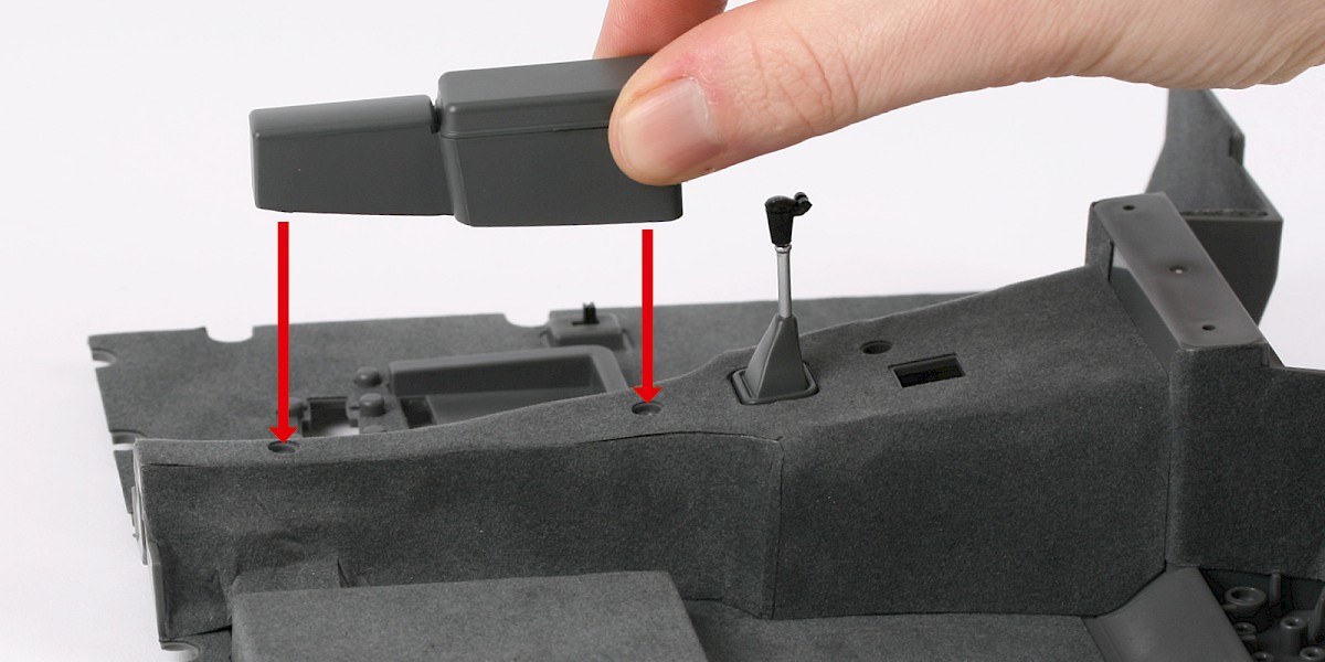
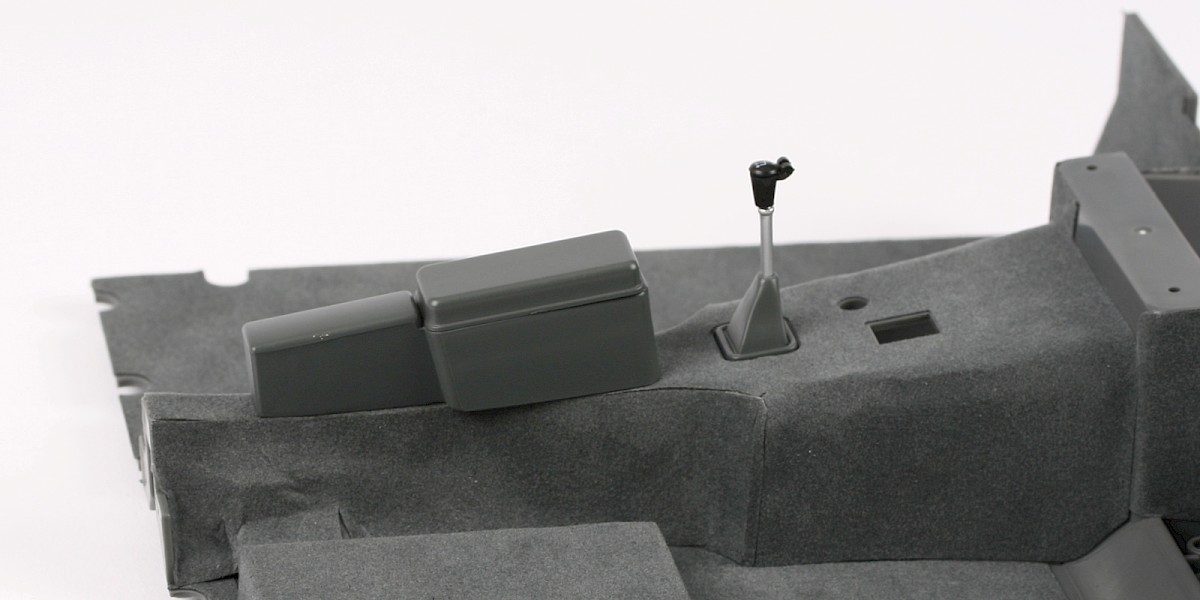
Fit the assembly to the cockpit floor.
Step 30
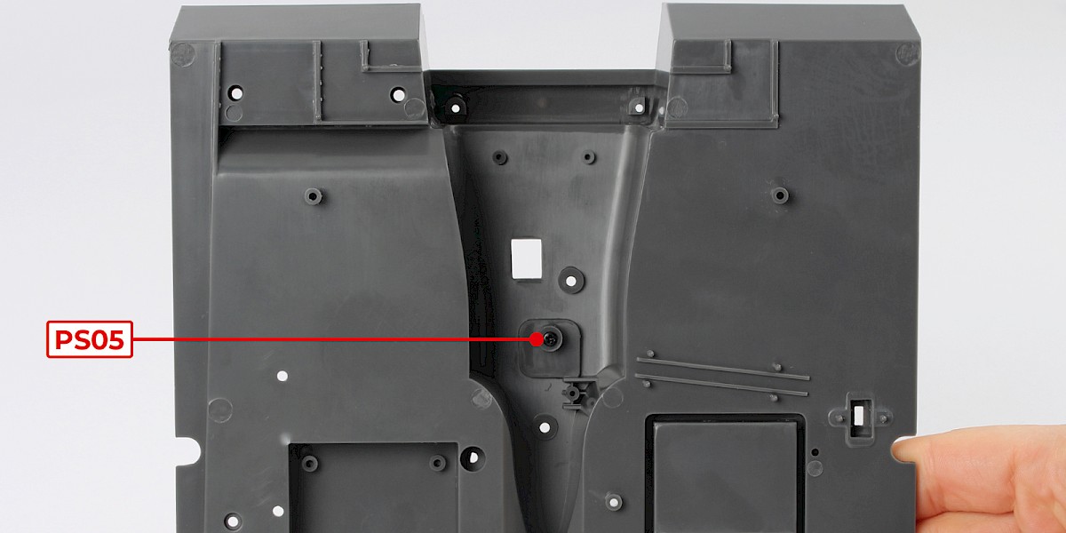
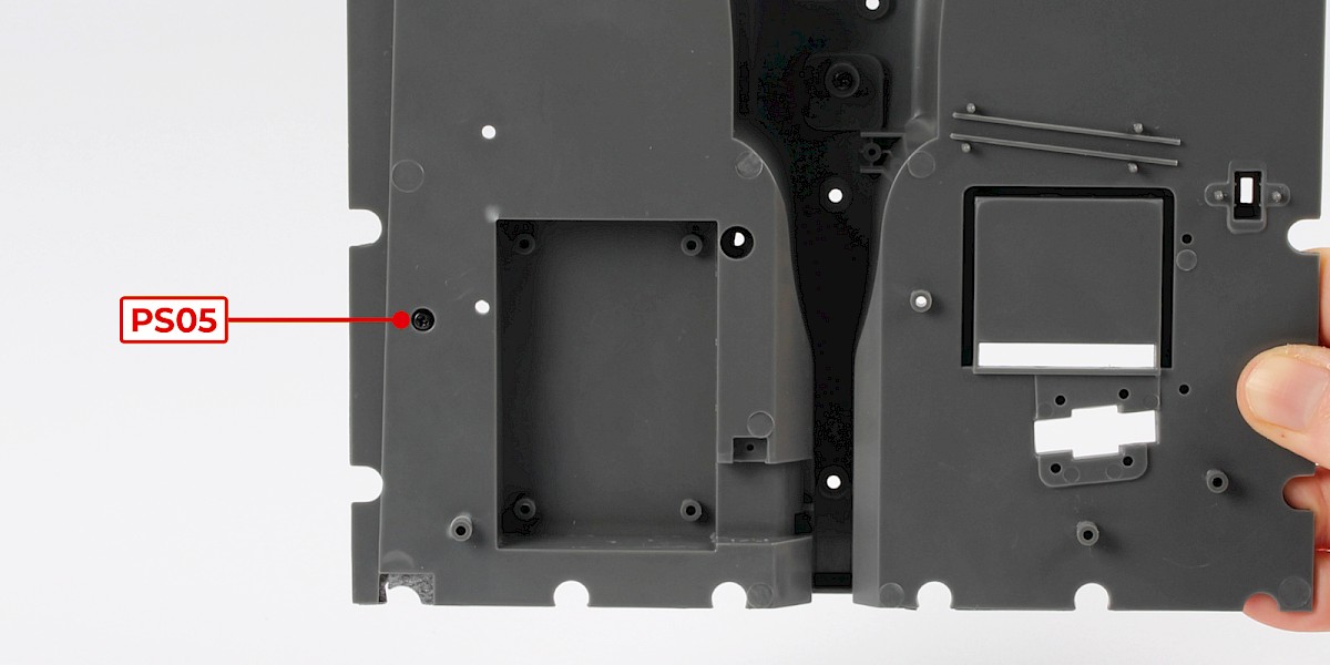
Secure from other side with 1x PS05.
Note: The gear stick parts are fragile. You may prefer to fit the gear stick assembly at a later stage.
Step 31
Fit the handbrake (43-D) to the cockpit floor.
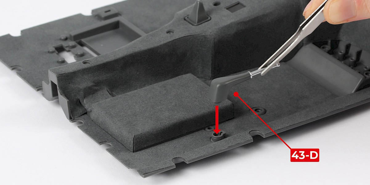
Step 32
Secure from the other side with 1x PS05.
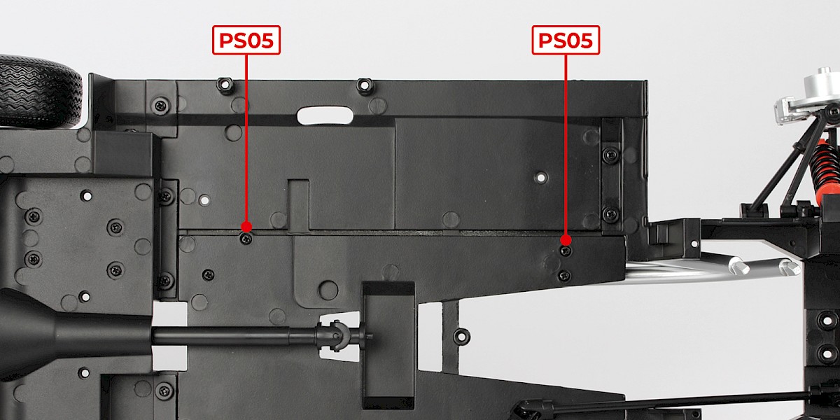
Step 33
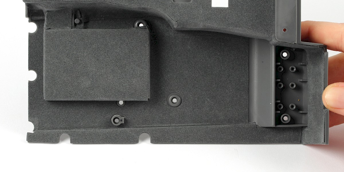
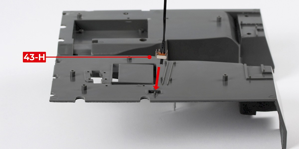
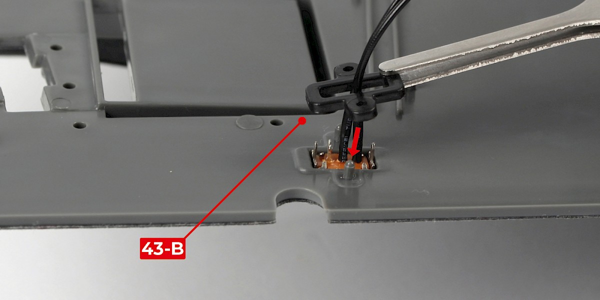
Push the power switch (43-H) into the cockpit floor.
Thread the power-switch plug through the power-switch bracket (43-B), then fit the power-switch bracket to the cockpit floor.
Step 34
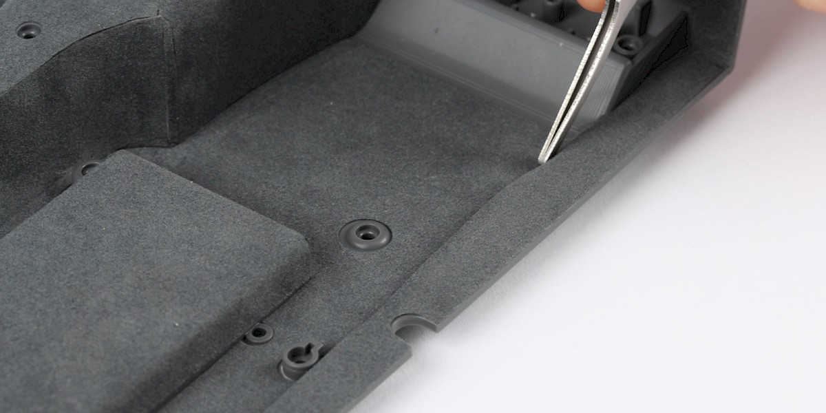
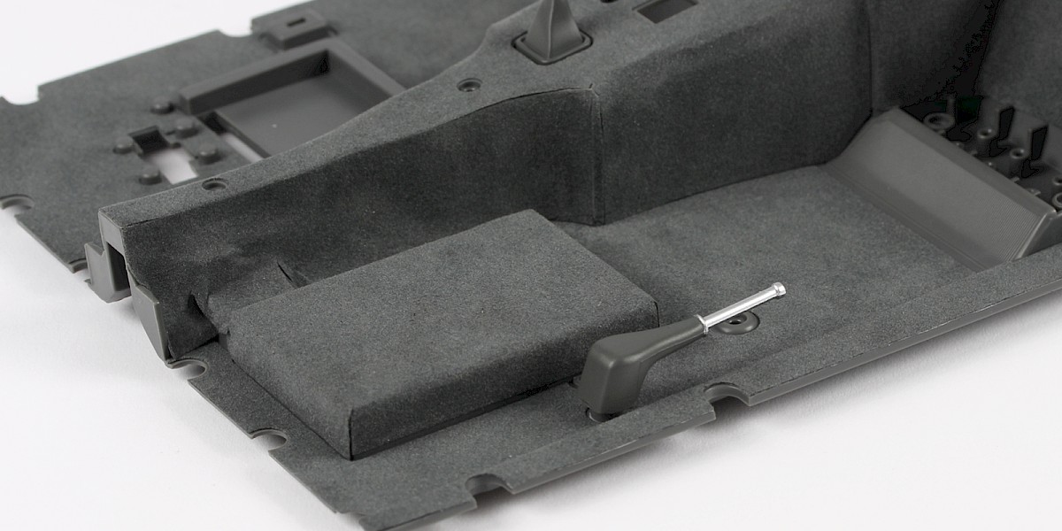
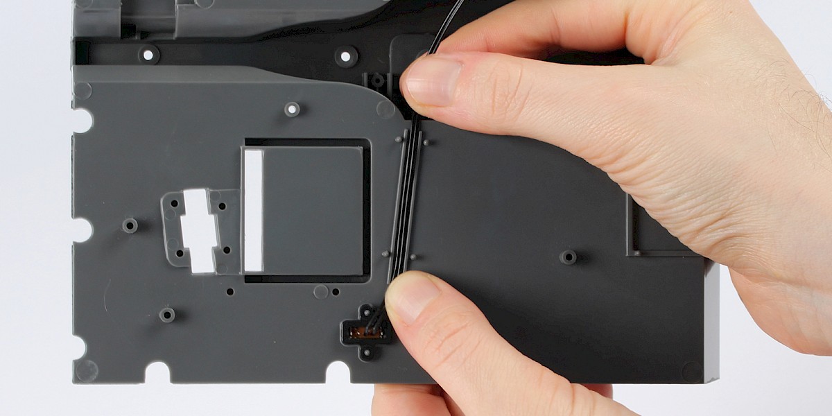
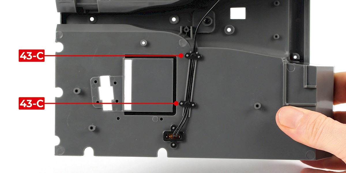
Position the power-switch cable into the channel as shown.
Secure the power-switch cable in place using 2x wire bracket (43-C).
STAGE COMPLETE

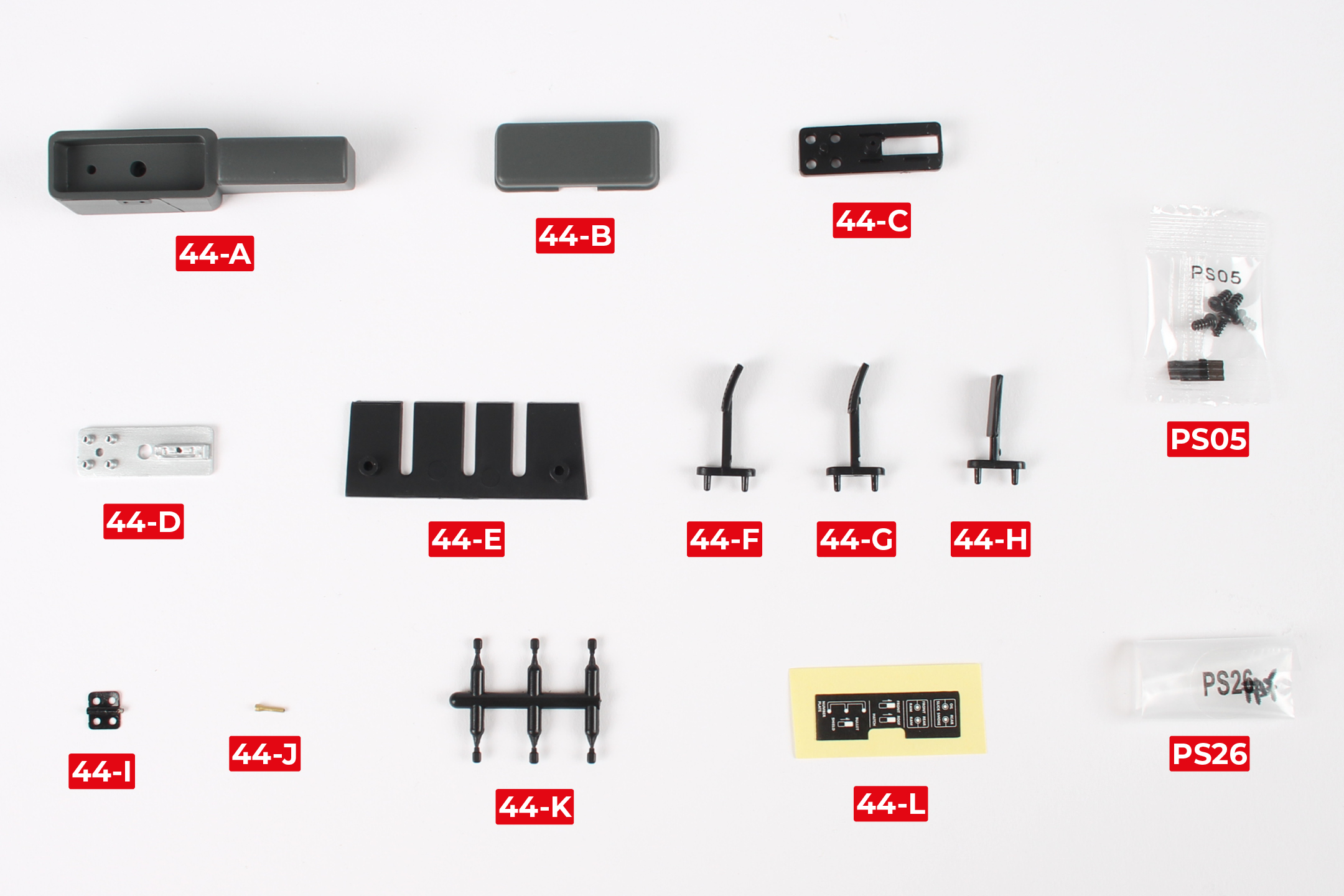
PARTS LIST
| 44-A Gadget-control console | 44-H Accelerator pedal |
| 44-B Gadget-control-console lid | 44-I Hinge |
| 44-C Upper panel | 44-J Lever |
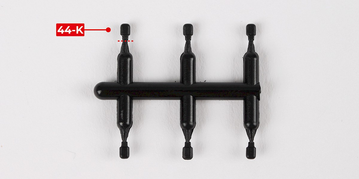
| 44-D Lower panel | 44-K Switch x6 |
| 44-E Pedal trim | 44-L Sticker |
| 44-F Clutch pedal | PS05 screws x5 |
| 44-G Brake pedal | PS26 screws x5 |
Step 1
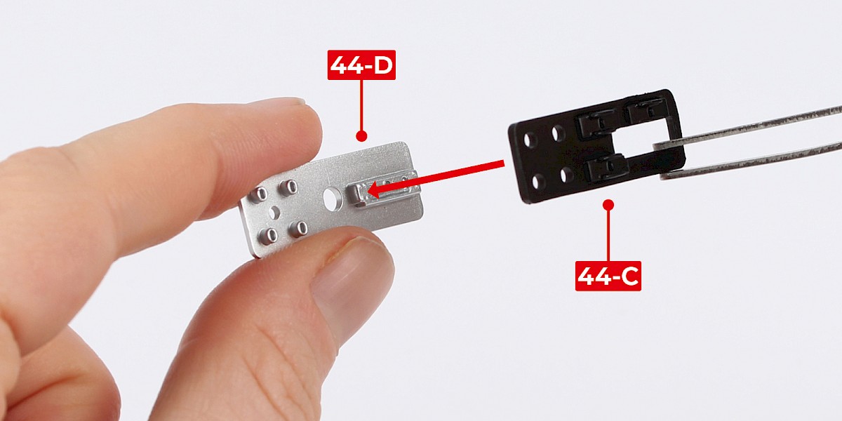
Fit the upper panel (44-C) onto the lower panel (44-D).
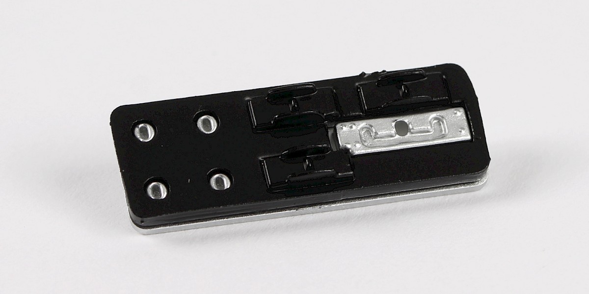
Step 2
Cut 1x switch (44-K) from the sprue.
Step 3
Fit the switch to the lower panel.
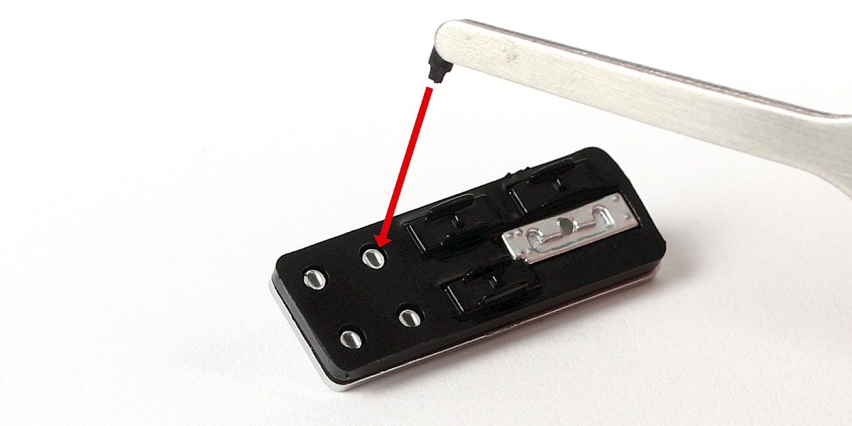
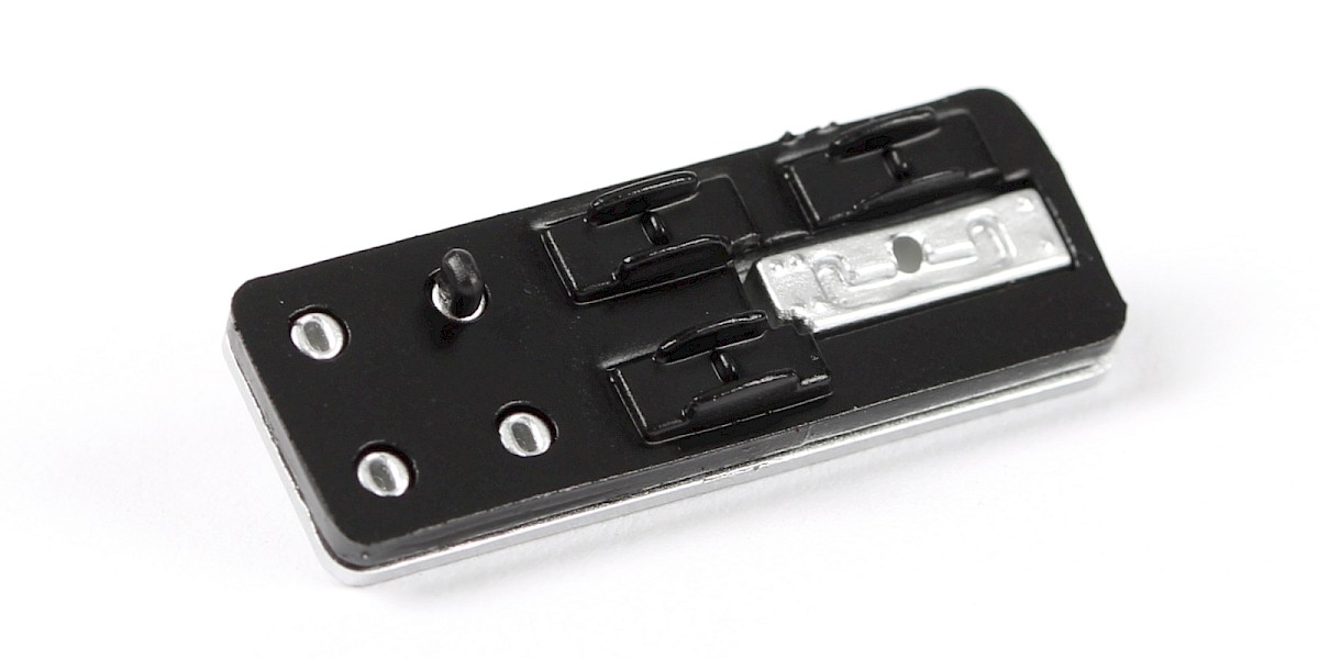
Step 4
Fit 3x switch as shown.
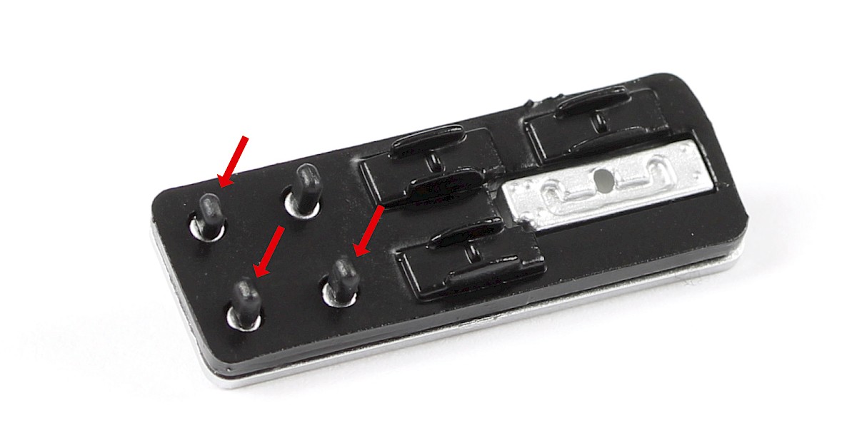
Step 5
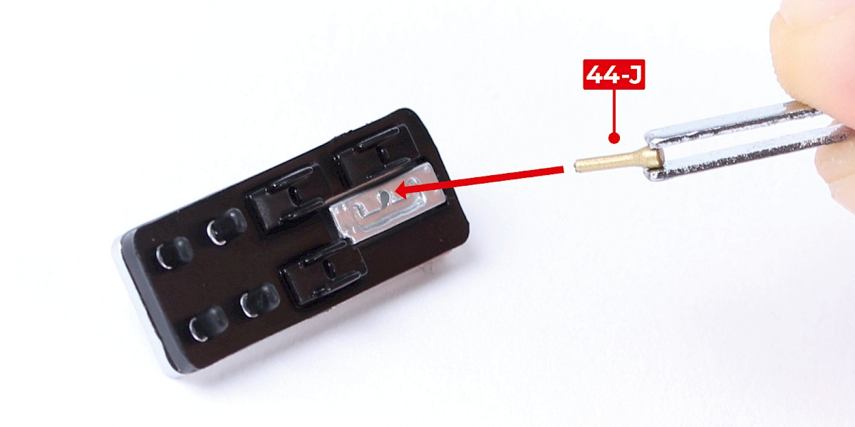
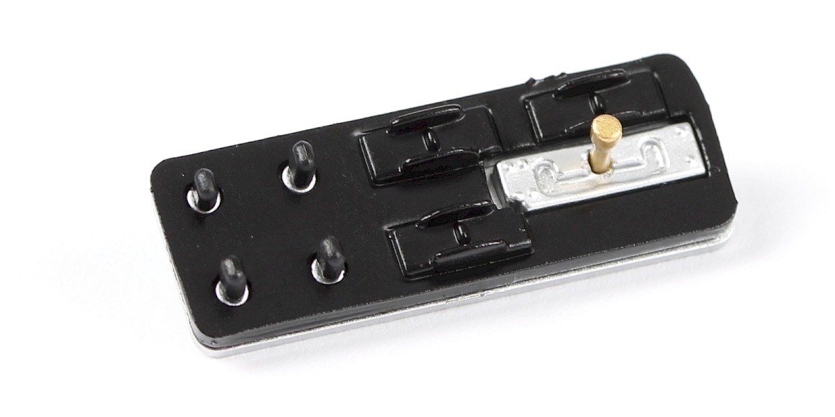
Fit the lever (44-J) to the lower panel.
Step 6
Fit the assembly into the gadget-control console (44-A).
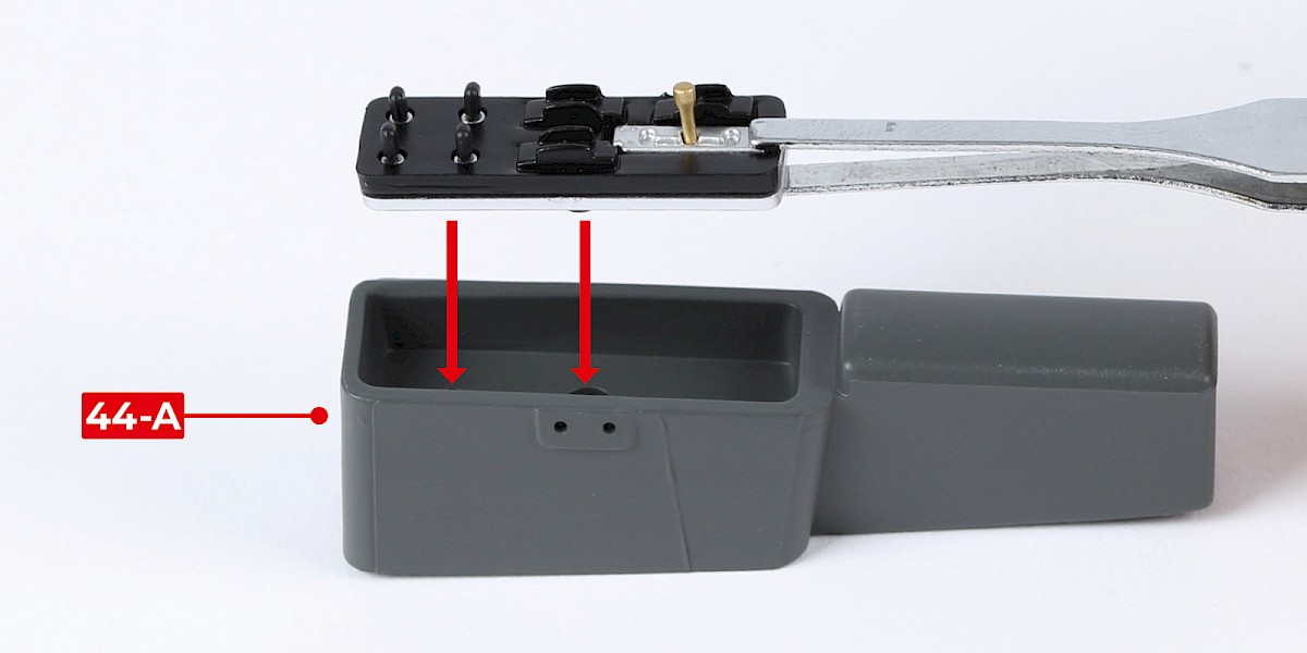
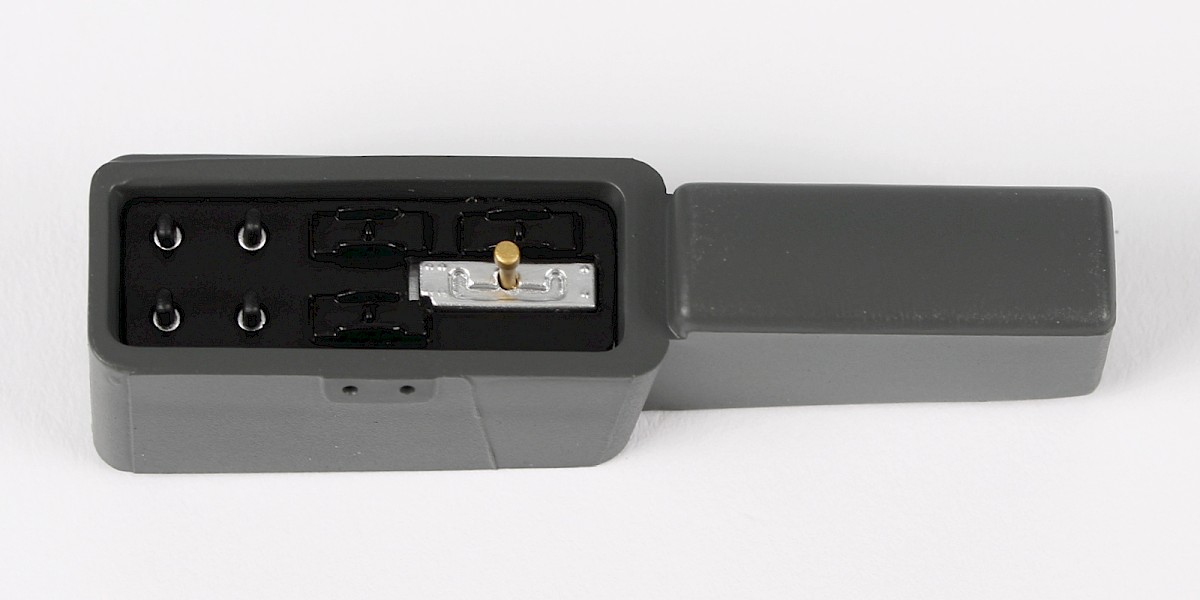
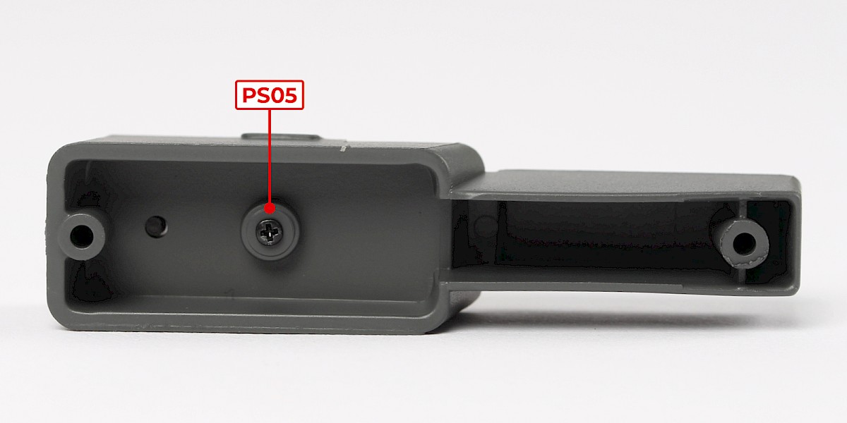
Step 7
Secure from other side with 1x PS05.
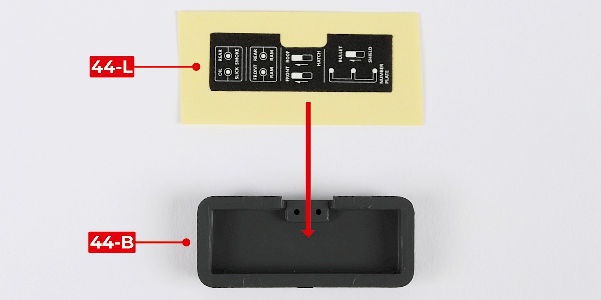
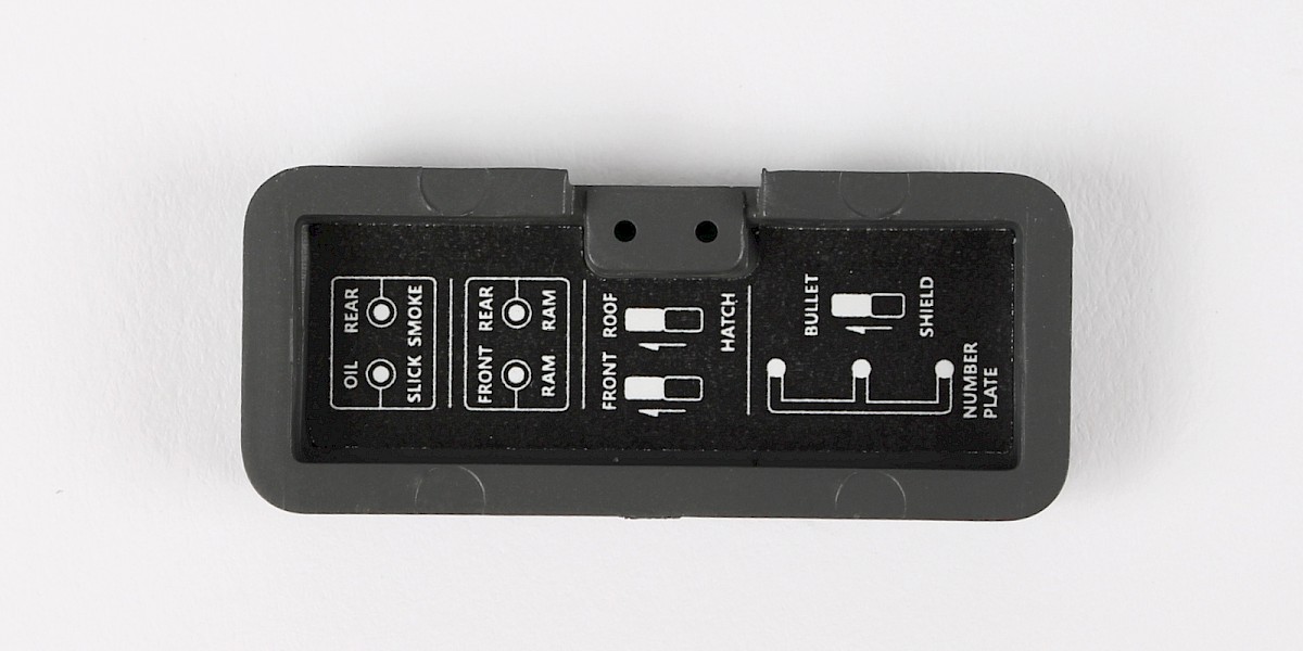
Step 8
Peel off the sticker (44-L) and stick it into the gadget-control-console lid (44-B).
Step 9
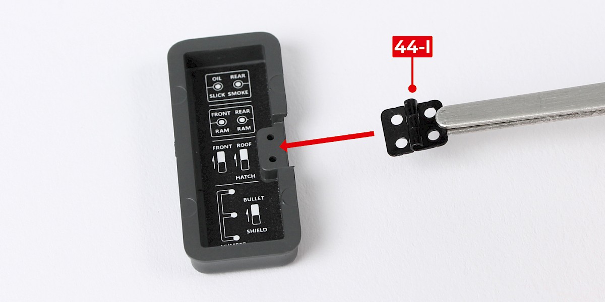
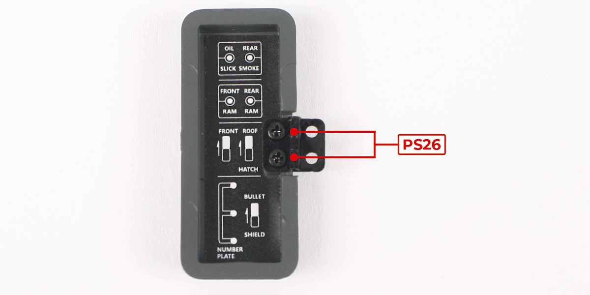
Position the hinge (44-I) on the gadget-control-console lid with the hinge-joint facing upwards.
Screw the parts together with 2x PS26.
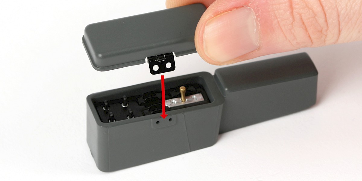
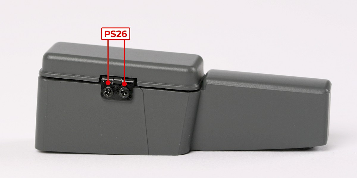
Step 10
Place the gadget-control-console lid on the gadget-control console.
Screw the parts together using 2x PS26.
Step 11
Fit the assembly onto the cockpit floor (stage 043).
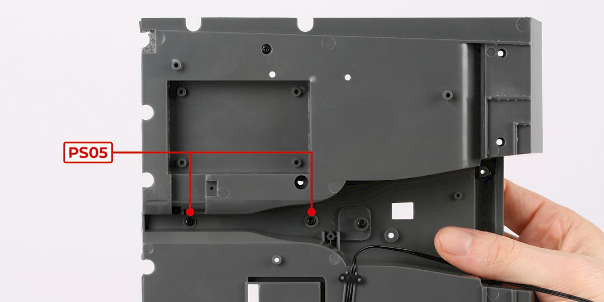
Step 12
Secure from the other side with 2x PS05.
Step 13
The foot-pedals and the cockpit floor are marked with 'A', 'B' and 'C'.
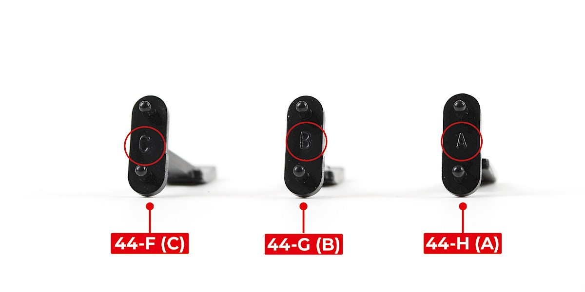
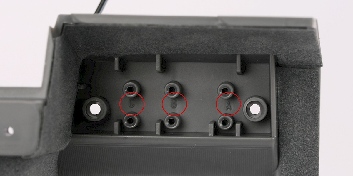
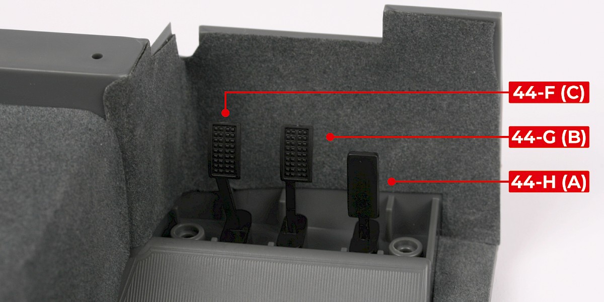
Step 14
Fit the clutch pedal (44-F), the brake pedal (44-G) and the accelerator pedal (44-H) in place.
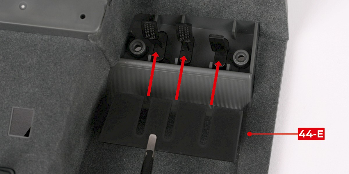
Step 15
Fit the pedal trim (44-E) in place as shown.
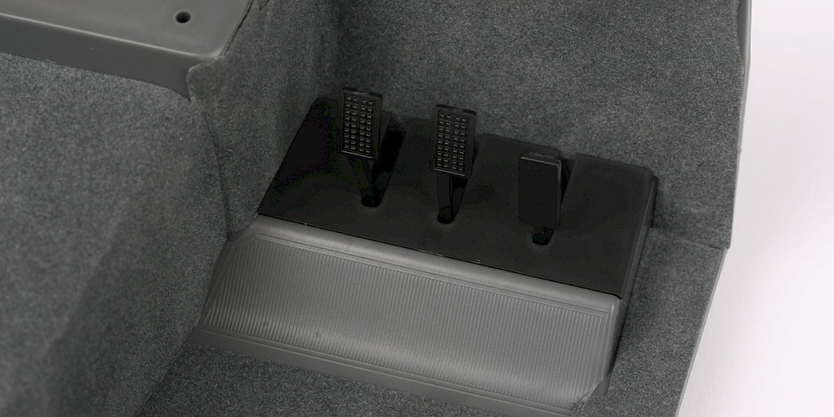
Step 16
Secure from the other side with 2x PS05.
STAGE COMPLETE
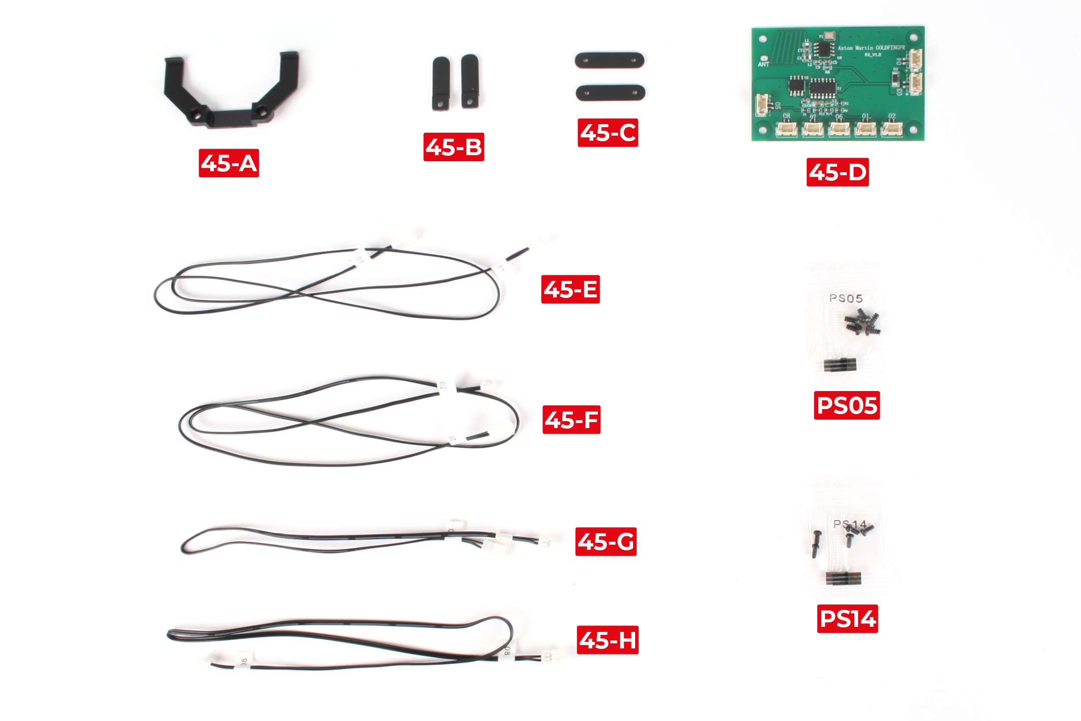
PARTS LIST
| 45-A Cable bracket | 45-F Cable No. 02 |
| 45-B Cable fastener x2 | 45-G Cable No. 05 |
| 45-C Cable clip x2 | 45-H Cable No. 08 |
| 45-D Circuit board | 5x PS05 screws |
| 45-E Cable No. 01 | 5x PS14 screws |
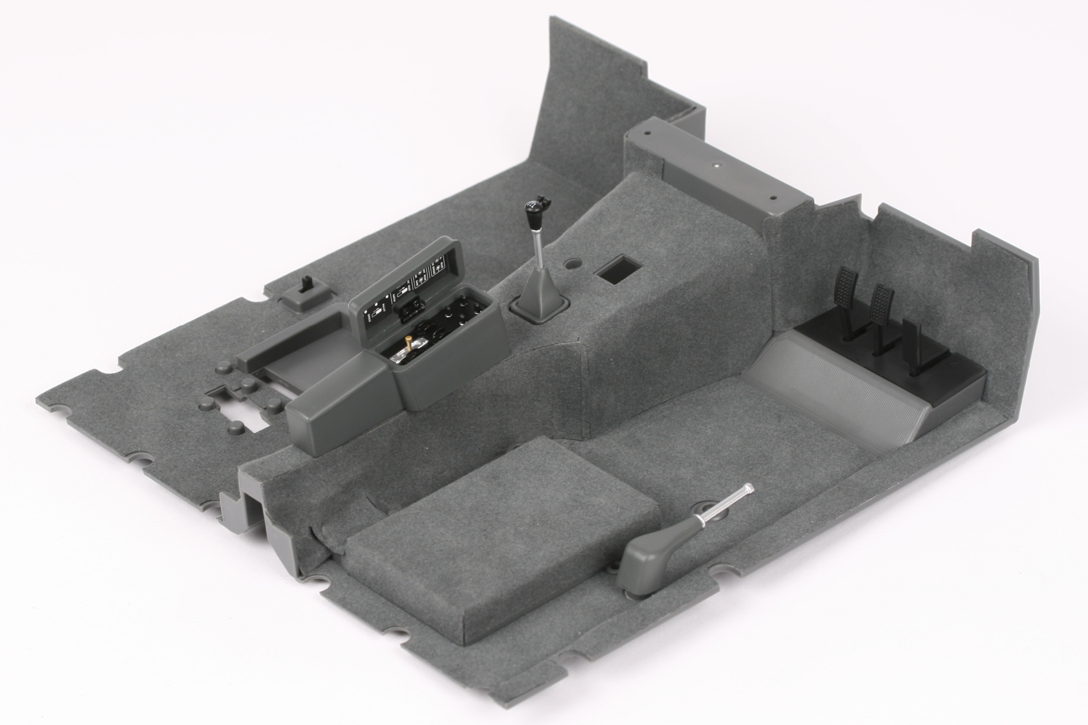
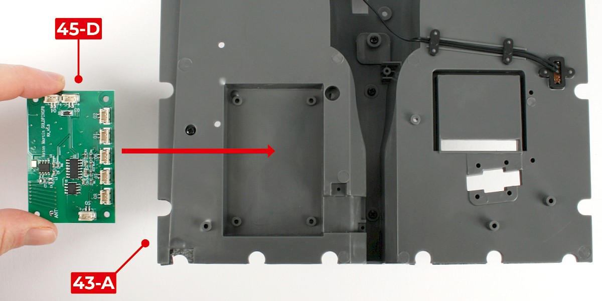
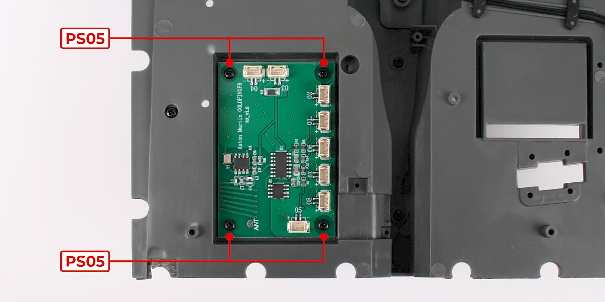
Step 1
Fit the circuit board (45-D) to the cockpit floor (stage 044).
Secure with 4x PS05.
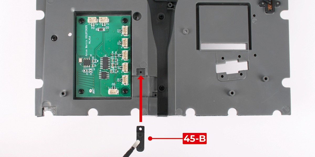
Step 2
Fit a cable fastener (45-B) to the cockpit floor.
Secure with 1x PS14.

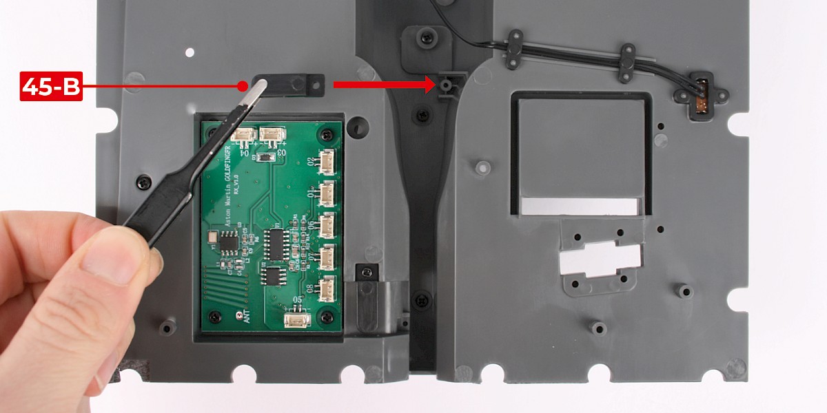
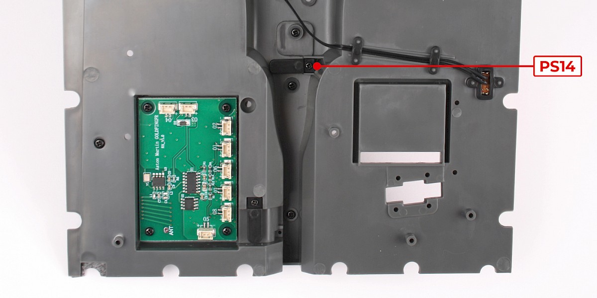
Step 3
Fit another cable fastener (45-B) to the cockpit floor.
Secure with 1x PS14.
Step 4
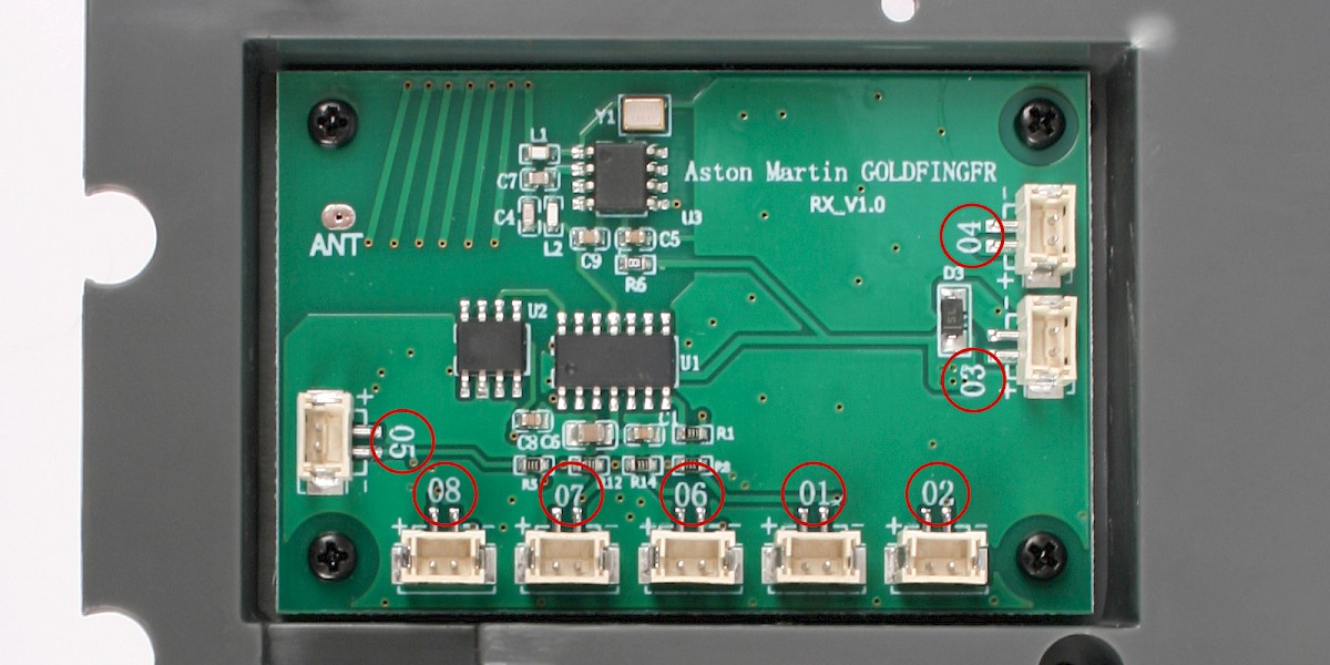
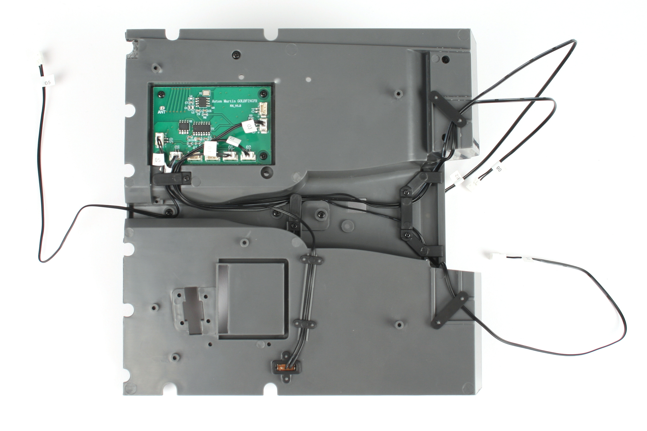
The sockets on the circuit board are marked with numbers which correspond to the cable numbers.
Step 5
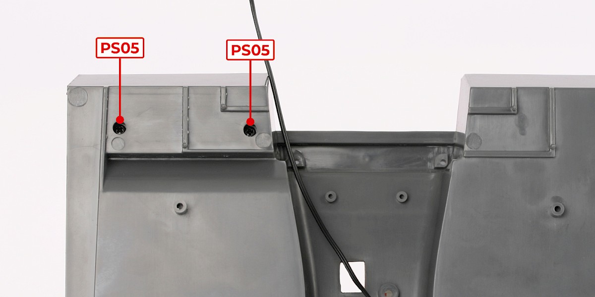
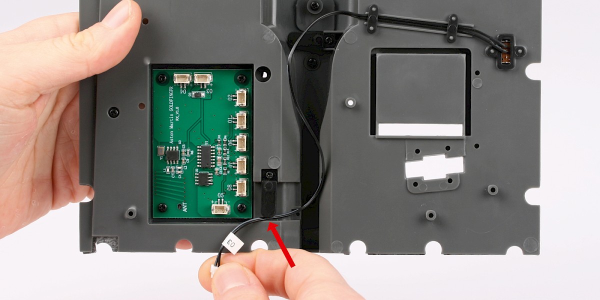
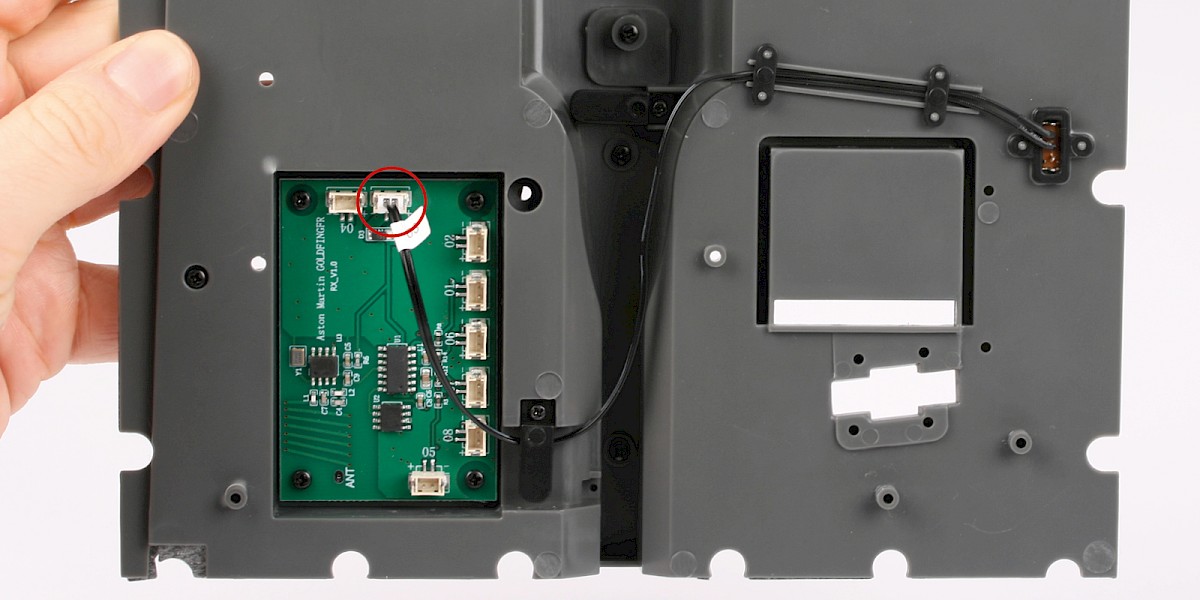
Fit the power-switch cable under the cable fastener (a).
Fit the power-switch plug into the socket marked '03' on the circuit board (b).
Step 6
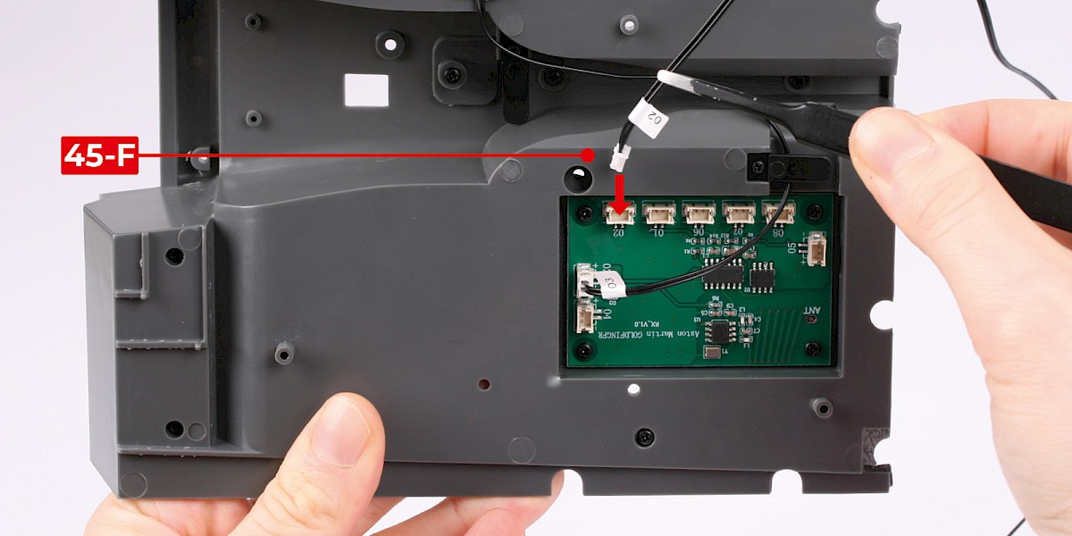
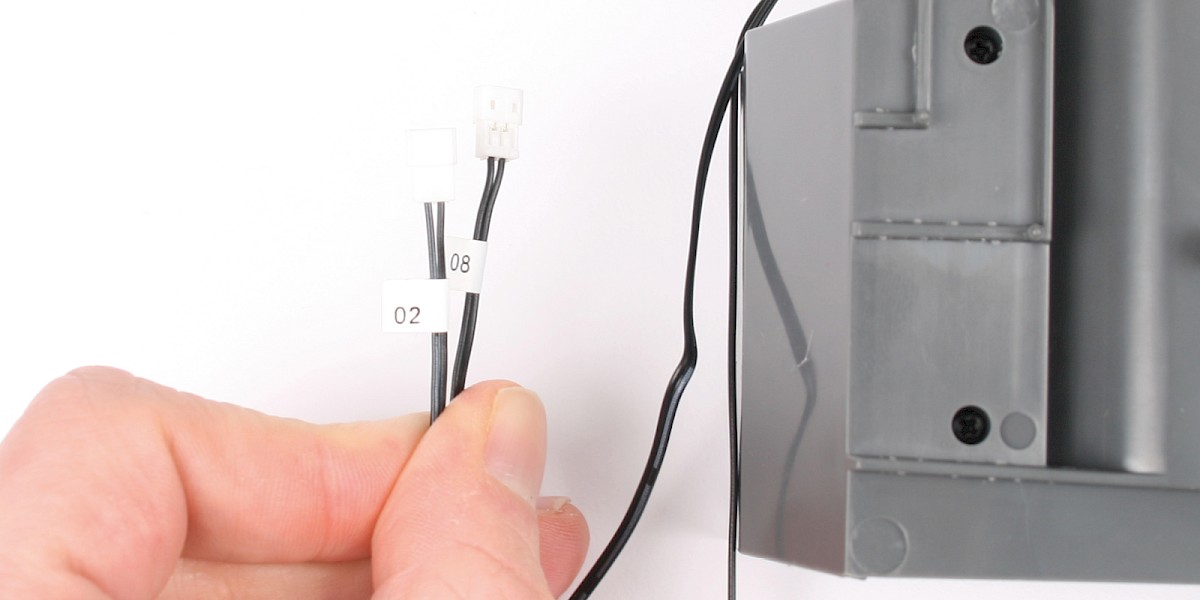
Plug the cable No. 02 (45-F) into the socket marked '02'.
Fit the cable No. 02 under the two cable fasteners as shown.
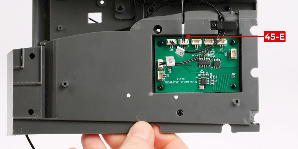
Step 7
Plug the cable No. 01 (45-E) into the socket marked '01'.
Fit the cable No. 01 under the two cable fasteners as shown.
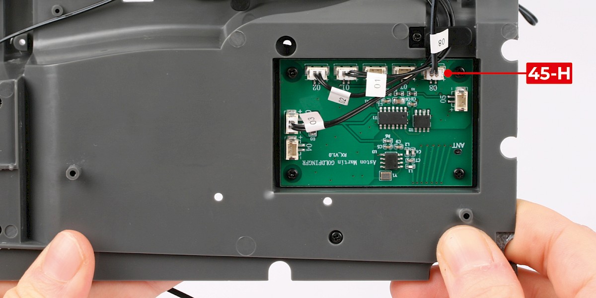
Step 8
Plug the cable No. 08 (45-H) into the socket marked '08'.
Fit the cable No. 08 under the two cable fasteners as shown.
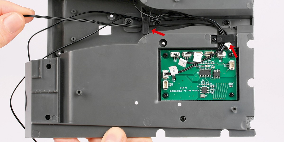
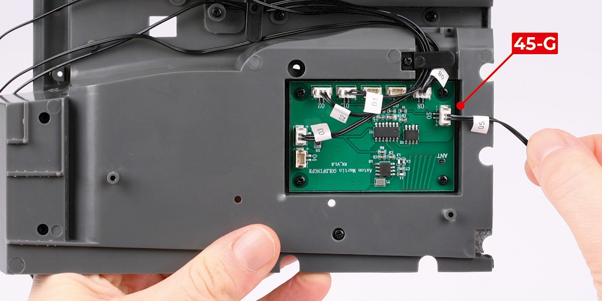
Step 9
Plug the cable No. 05 (45-G) into the socket marked '05'.
Fit the cable No. 05 under the fastener.
Direct the cable No. 05 towards the rear of the cockpit floor as shown.

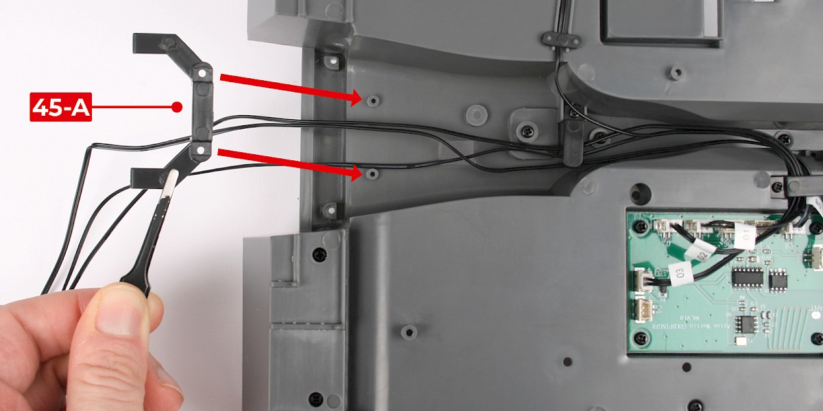
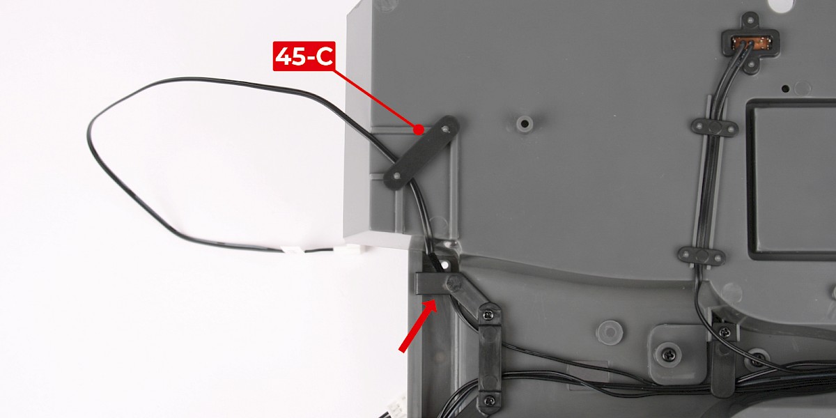
Step 10
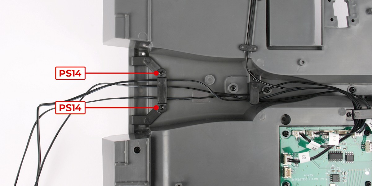
Place the cable bracket (45-A) over the cable No. 01, the cable No. 02 and the cable No. 08. Fit the cable bracket (45-A) to the cockpit floor.
Secure with 2x PS14.
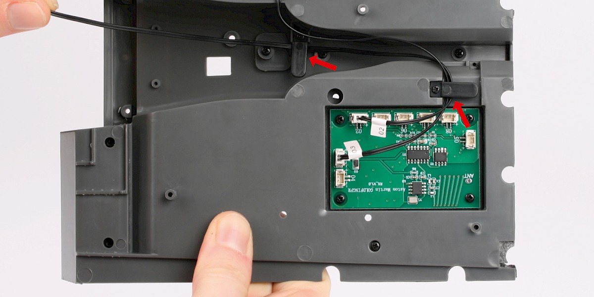
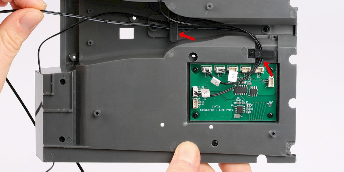
Step 11
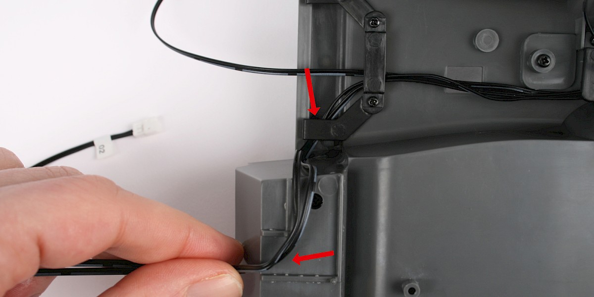
Fit cable No. 02 and cable No. 08 under the cable bracket as shown.
Place cable No. 02 and cable No. 08 in the channel, as shown by the red arrows.
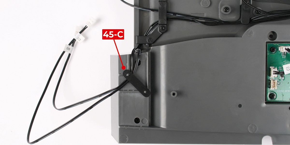
Step 12
Secure cable No. 02 and cable No. 08 in place with a cable clip (45-C).
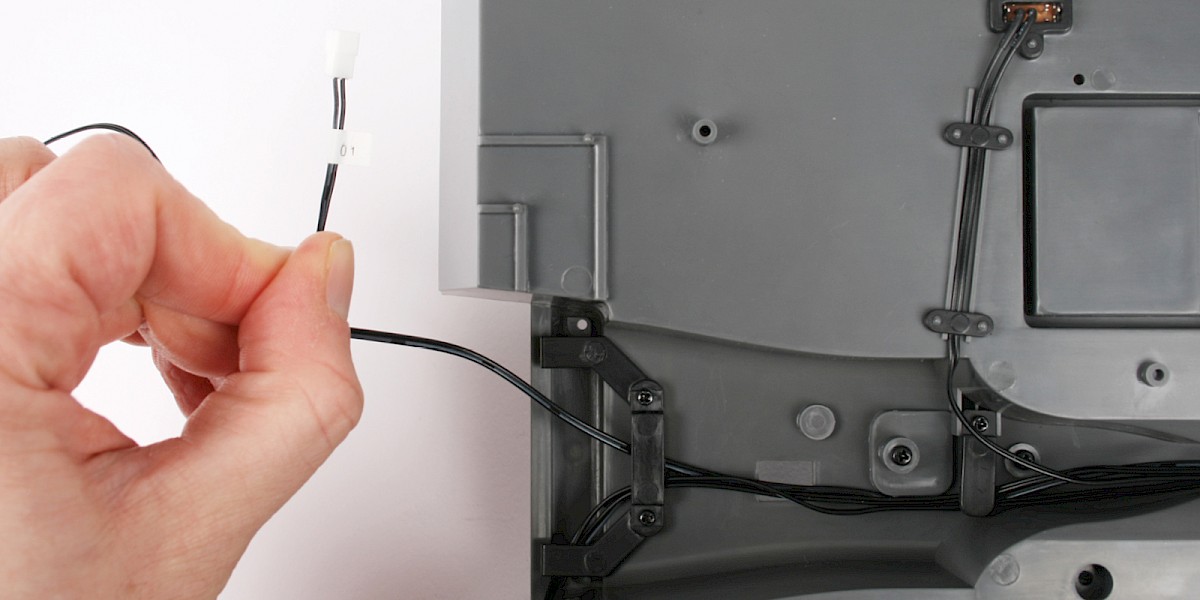
Step 13
Repeat on the opposite side to position cable No. 01.
Secure cable No. 01 with the another cable clip (45-C).
STAGE COMPLETE
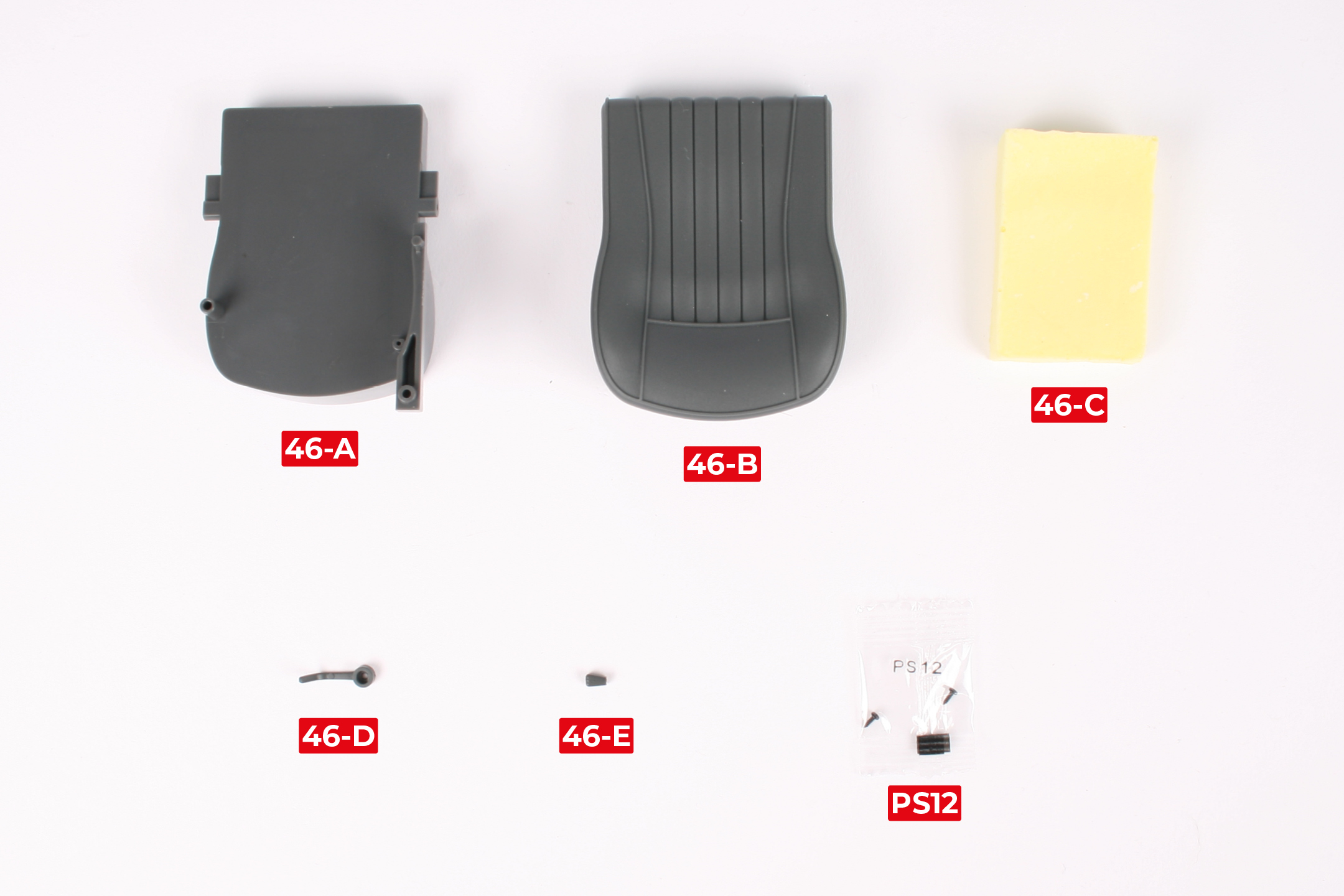
PARTS LIST
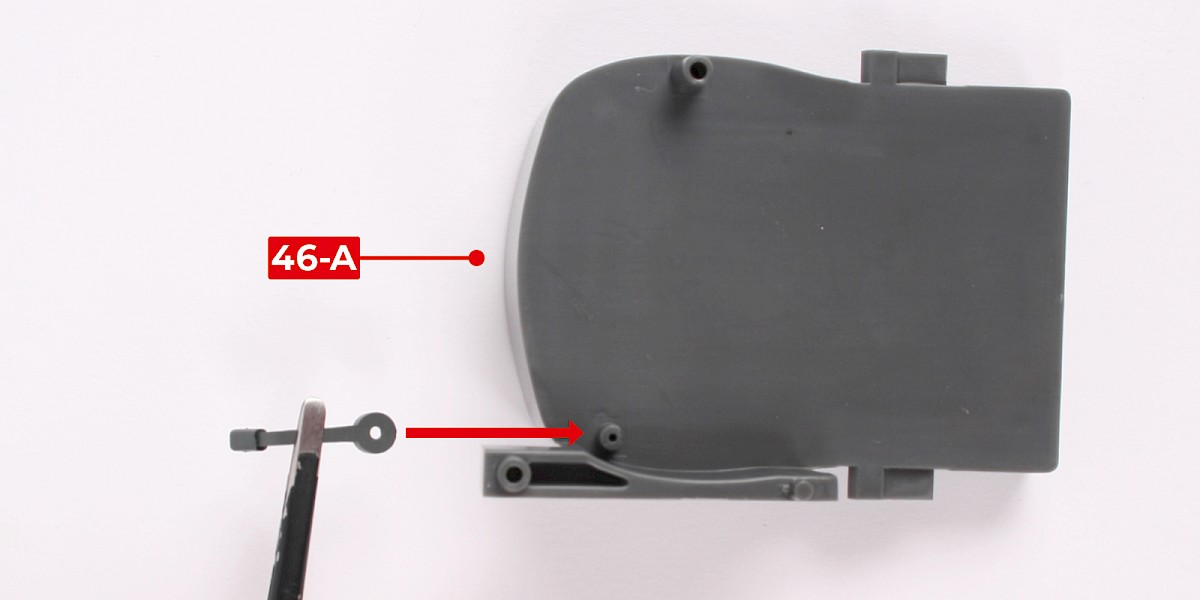
| 46-A Seat base |
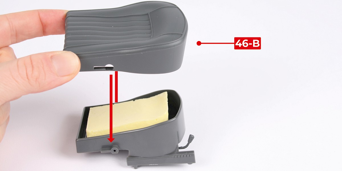
| 46-B Seat cover |
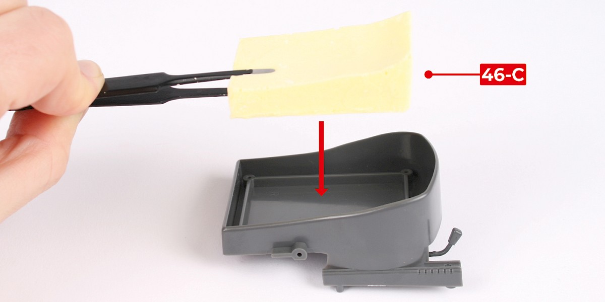
| 46-C Seat cushion |
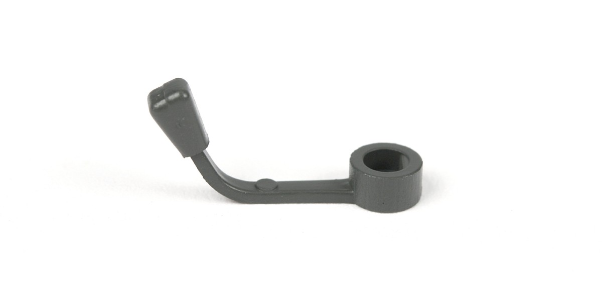
| 46-D Adjustment lever |
| 46-E Adjustment lever handle |
| 2x PS12 screws |
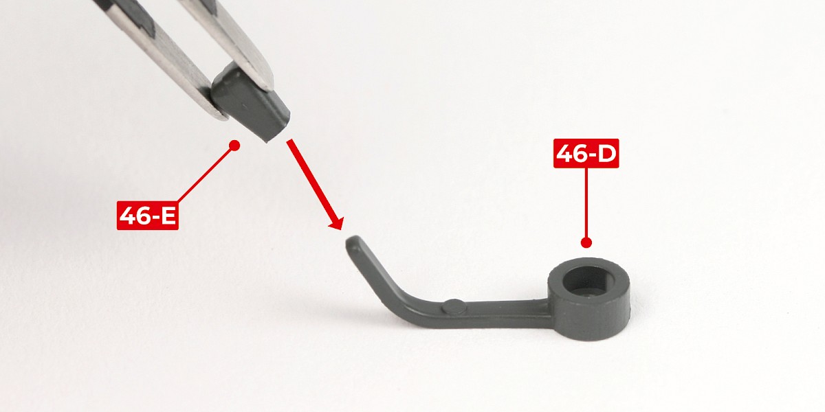
Step 1
Fit the adjustment lever handle (46-E) onto the adjustment lever (46-D).
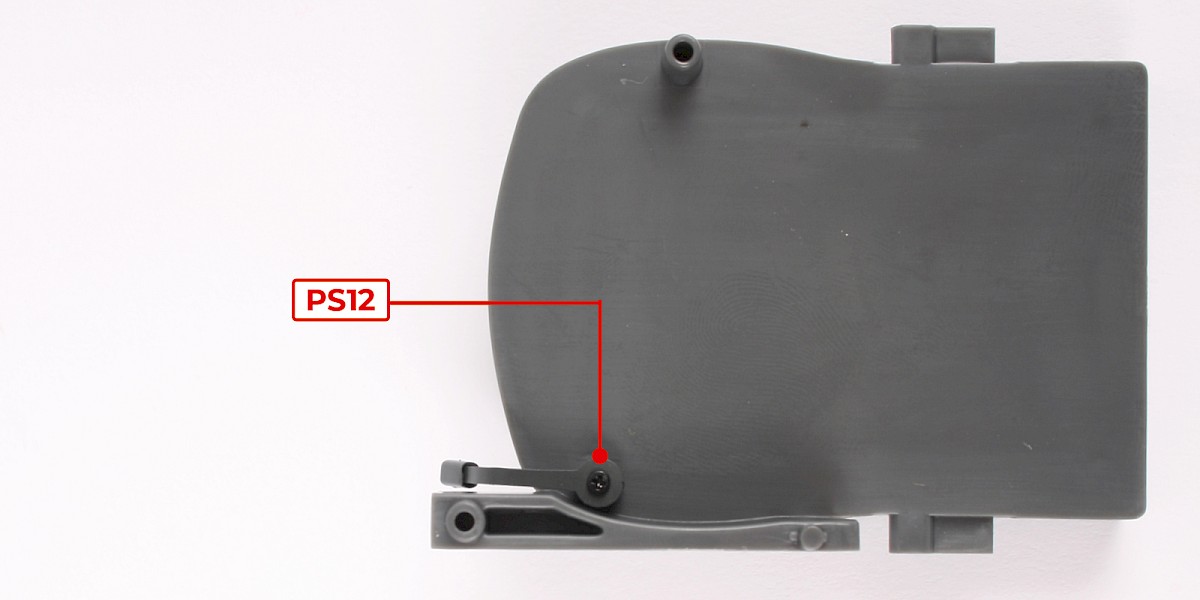
Step 2
Fit the adjustment lever onto the seat base (46-A).
Secure with 1x PS12.
Step 3
Place the seat cushion (46-C) onto the seat base.
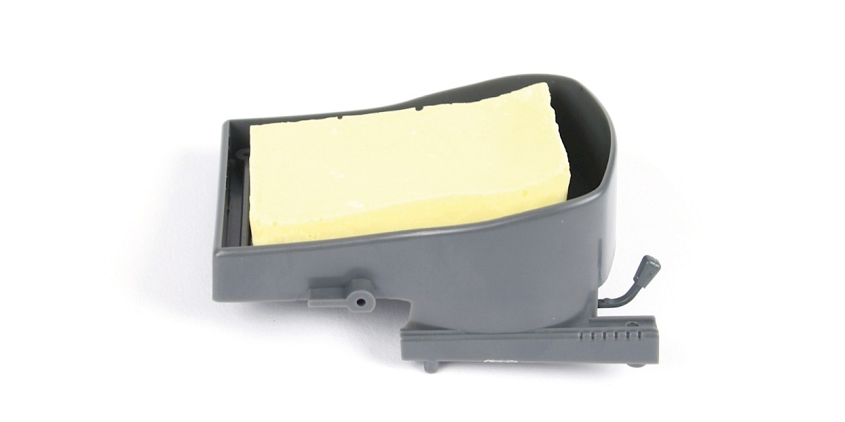
Step 4
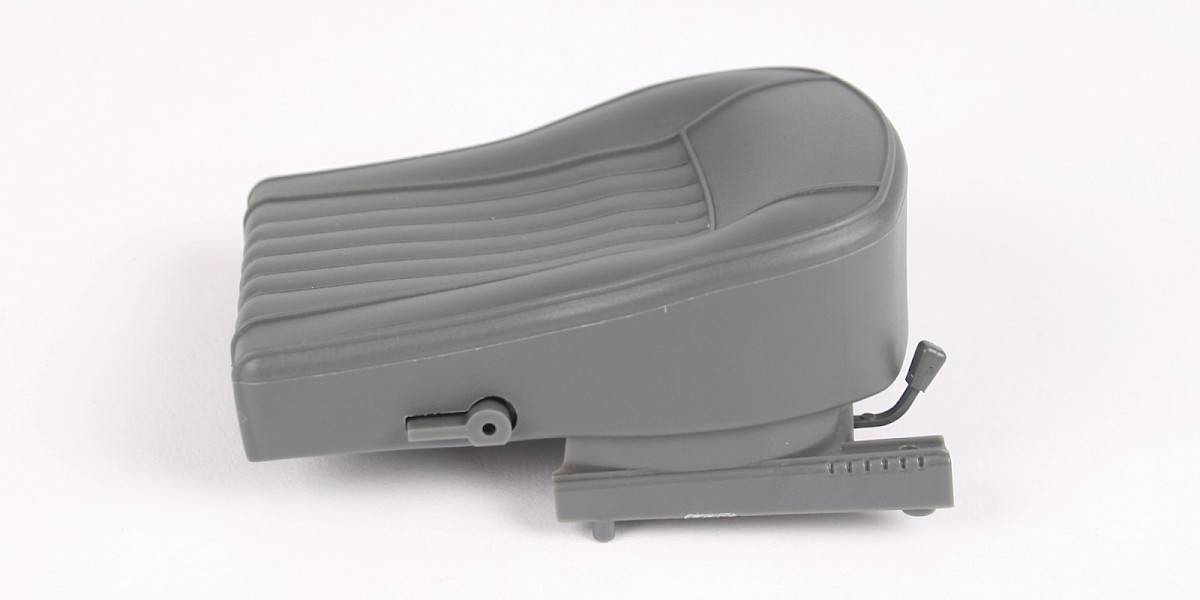
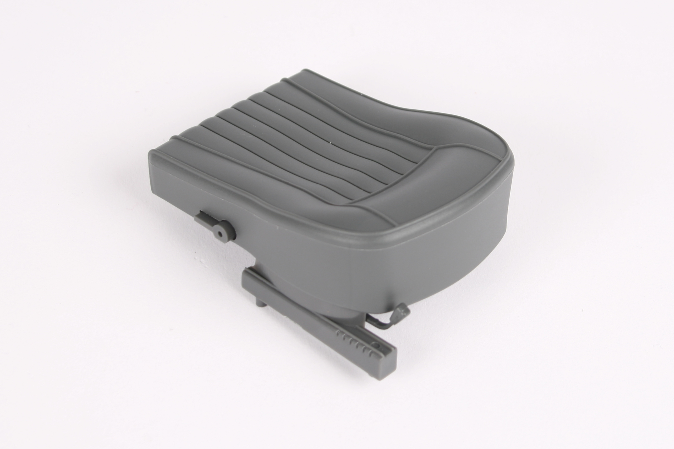
Fit the seat cover (46-B) onto the seat base.
STAGE COMPLETE
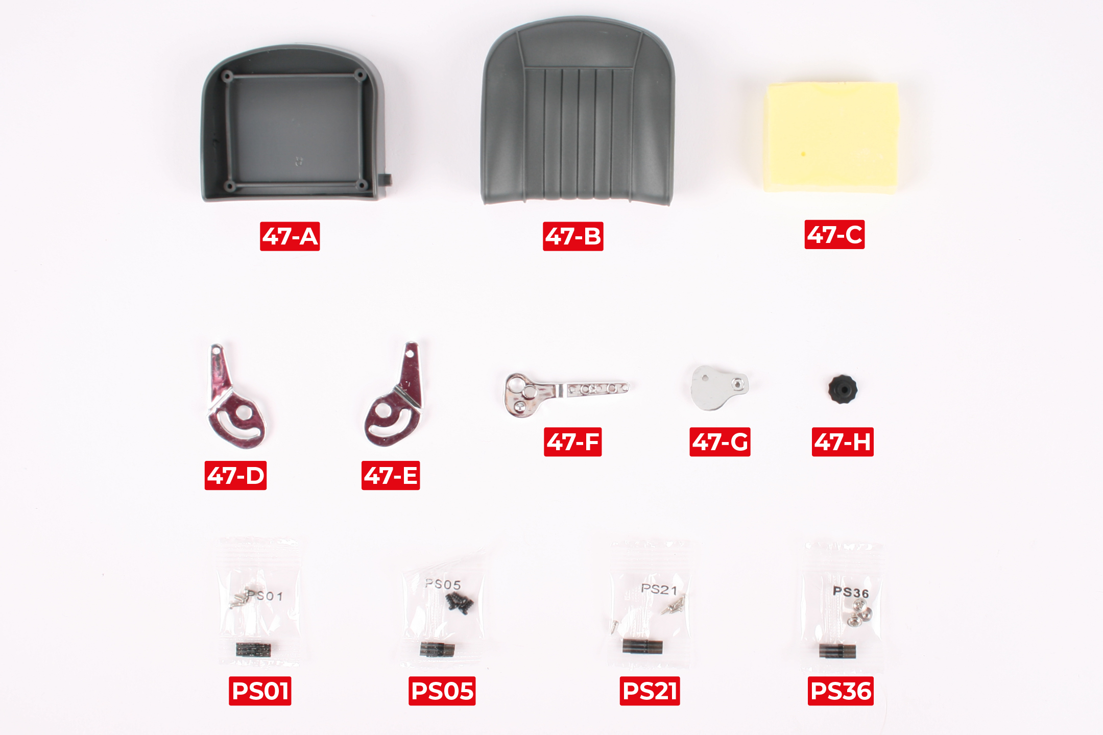
PARTS LIST
| 47-A Backrest | 47-G Seat tilt hinge (R1) |
| 47-B Backrest cover | 47-H Backrest adjustment wheel |
| 47-C Backrest cushion | 3x PS01 screws |
| 47-D Backrest tilt hinge (R1) | 3x PS05 screws |
| 47-E Backrest tilt hinge (R2) | 5x PS21 screws |
| 47-F Seat tilt hinge (R2) | 3x PS36 screws |
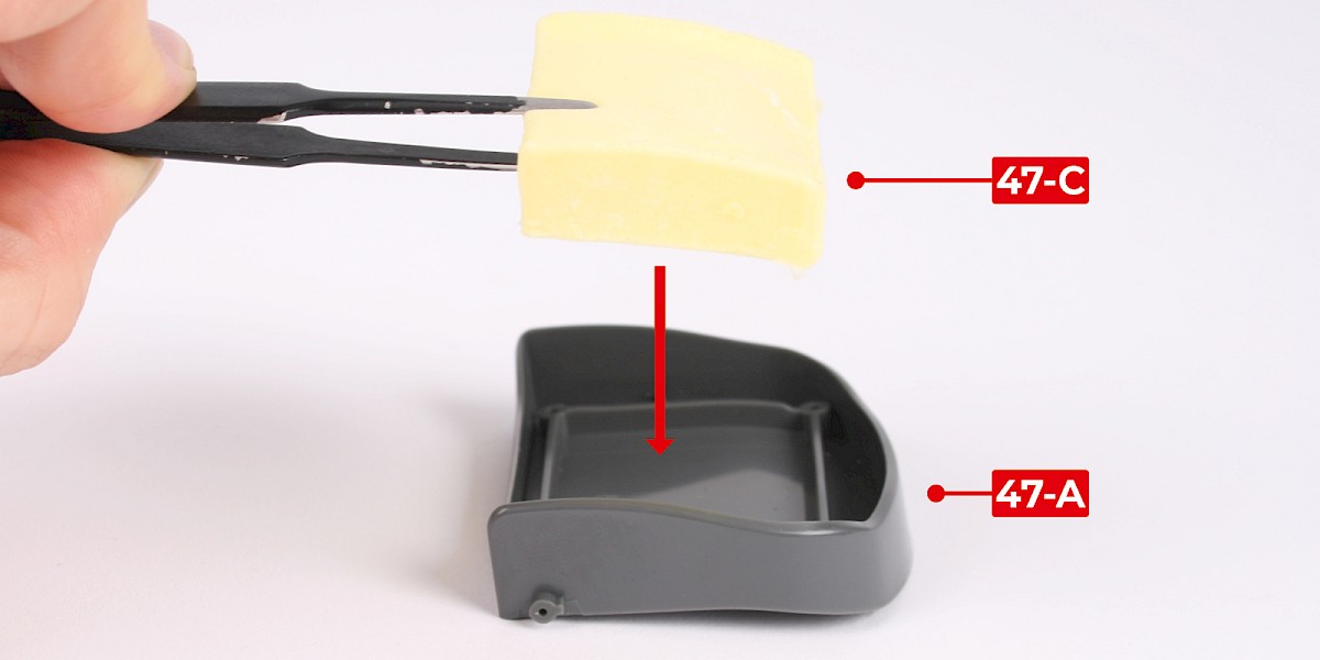
Step 1
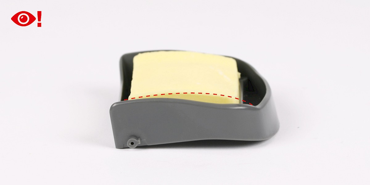
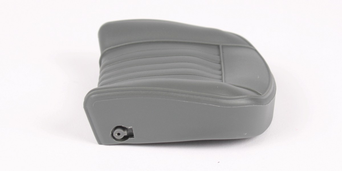
Place the backrest cushion (47-C) onto the backrest (47-A).
The backrest cushion should match the curve of the backrest, as shown by the dashed red line.
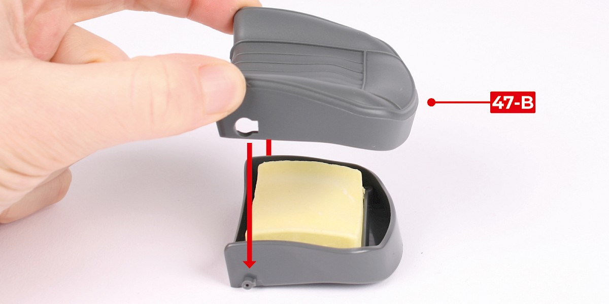
Step 2
Fit the backrest cover (47-B) onto the backrest.
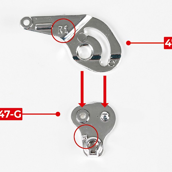
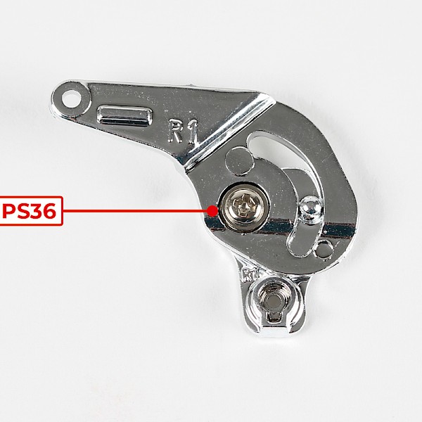
Step 3
Fit the backrest tilt hinge (47-D) onto the seat tilt hinge (47-G). Both parts are marked with 'R1'.
Screw the parts together with 1x PS36.
Step 4
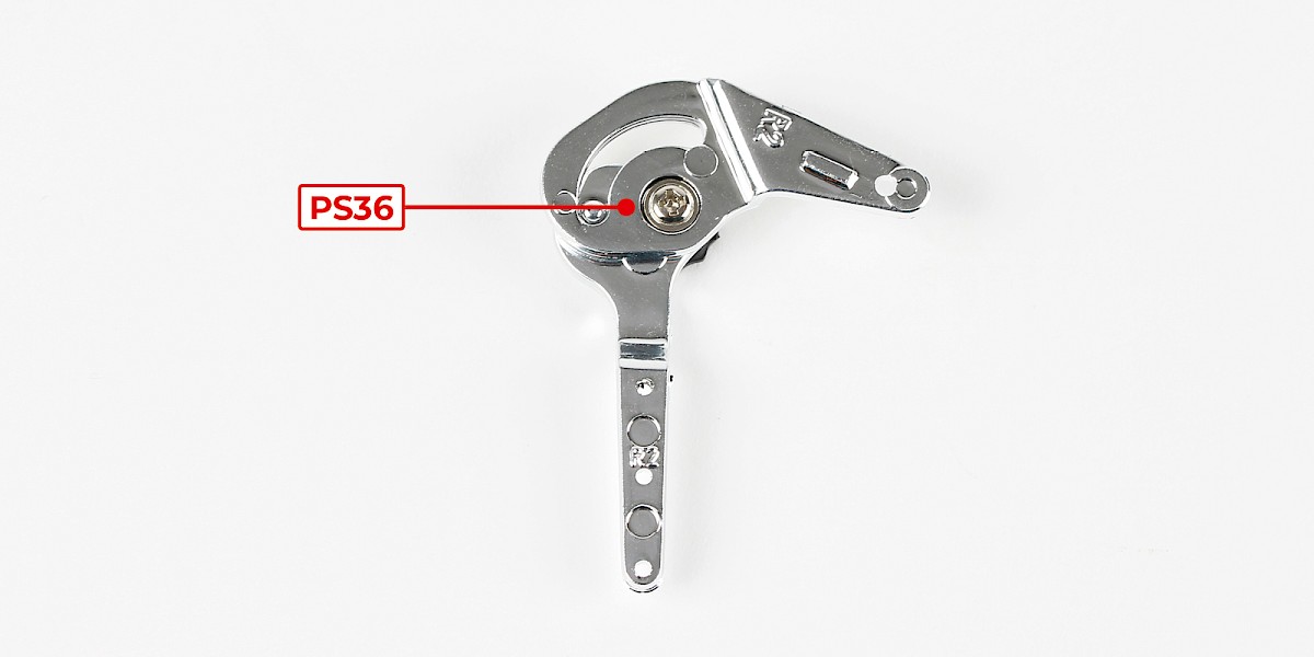
Fit the seat tilt hinge (47-F), marked 'R2', to the backrest adjustment wheel (47-H).
Fit the backrest tilt hinge (47-E), marked 'R2', to the assembly.

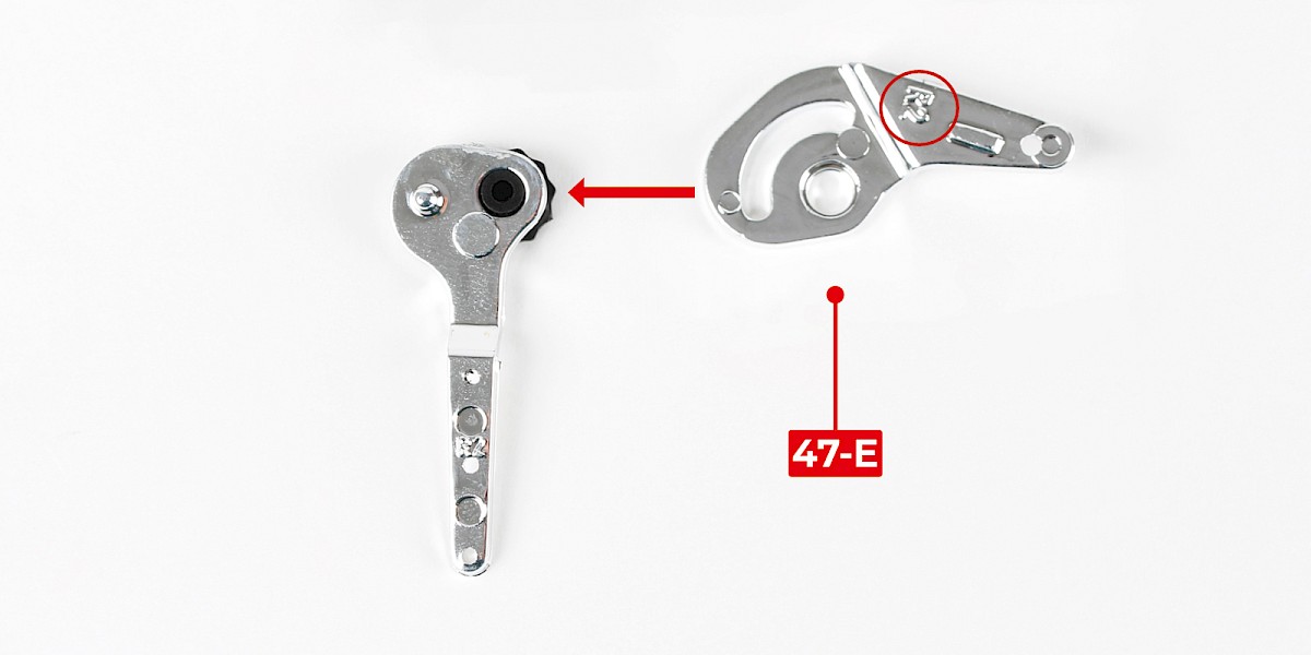
Step 5
Screw the parts together with 1x PS36.
Don't overtighten the screw, the parts should be able to move as shown.
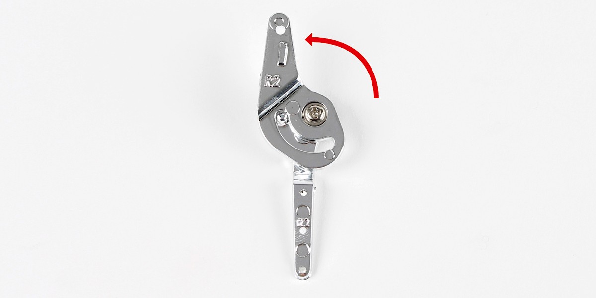
Step 6
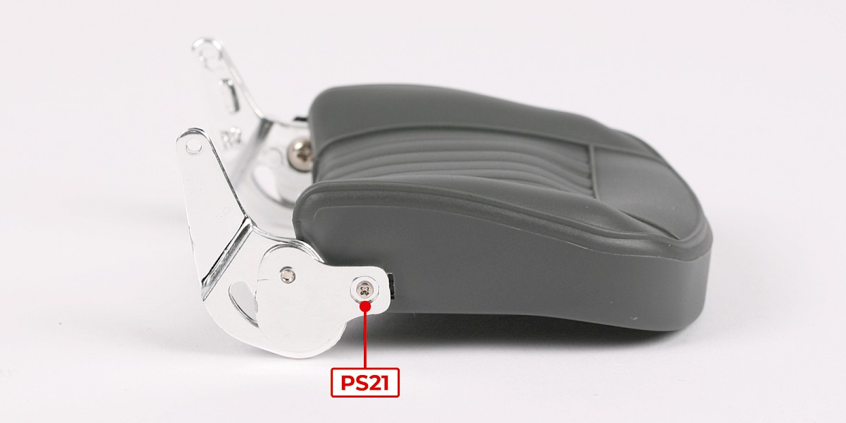
Fit the assembly onto the backrest.
Secure with 3x PS21.

Step 7
Fit the backrest tilt hinge (from step 3) to the other side.
Secure with 1x PS21.
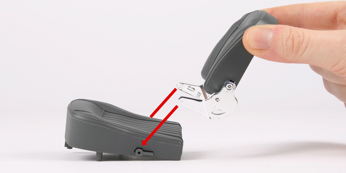
Step 8
Fit the assembly to the seat base (stage 046).
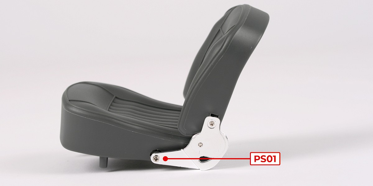
Step 9
Secure using 2x PS01.
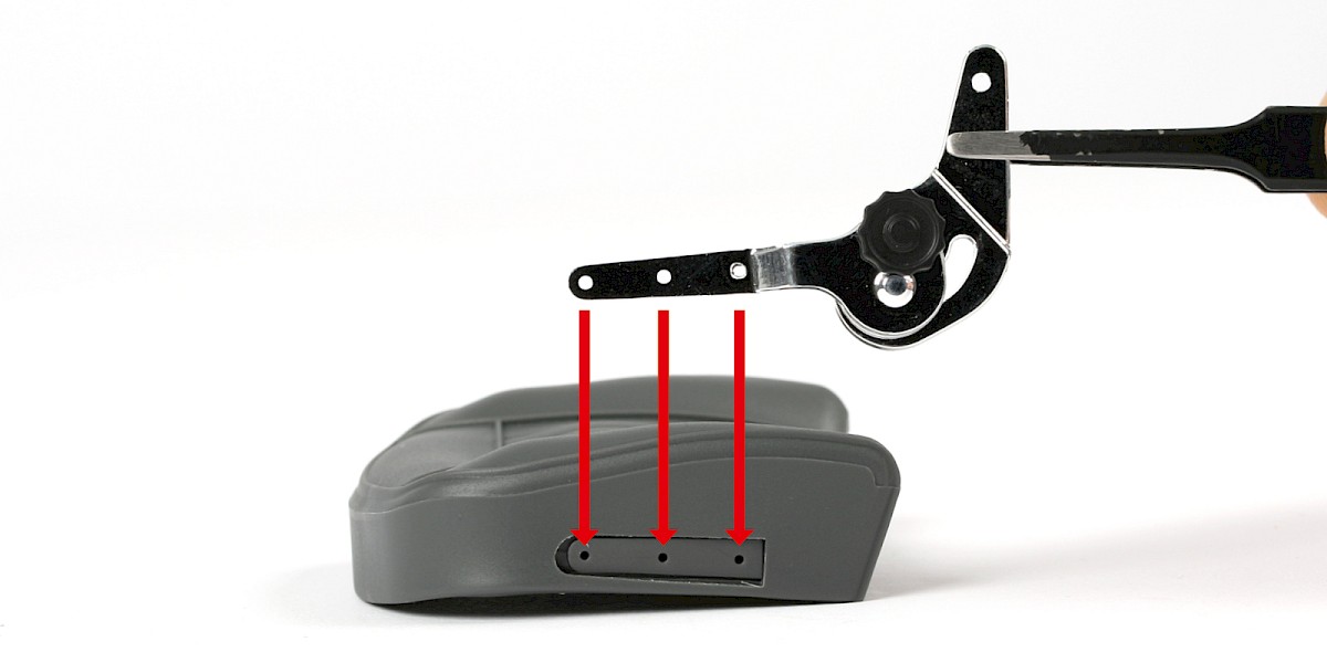
Step 10
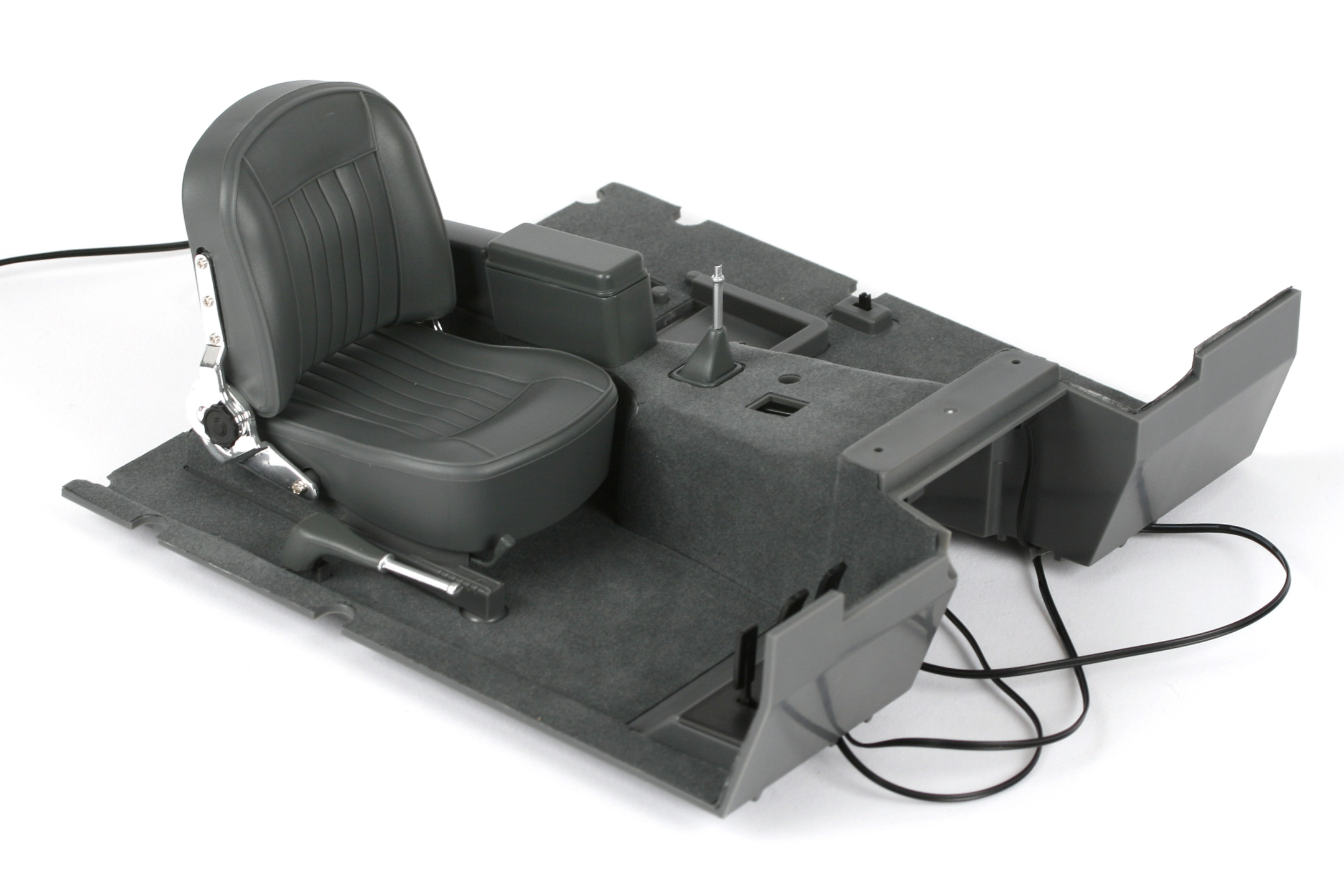
Take the cockpit floor (stage 045) and locate the three holes for the driver's seat.
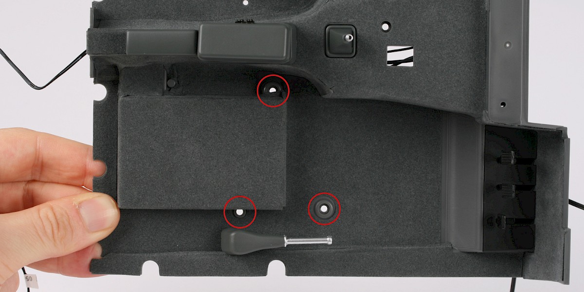
Step 11
Fit the driver's seat to the cockpit floor.
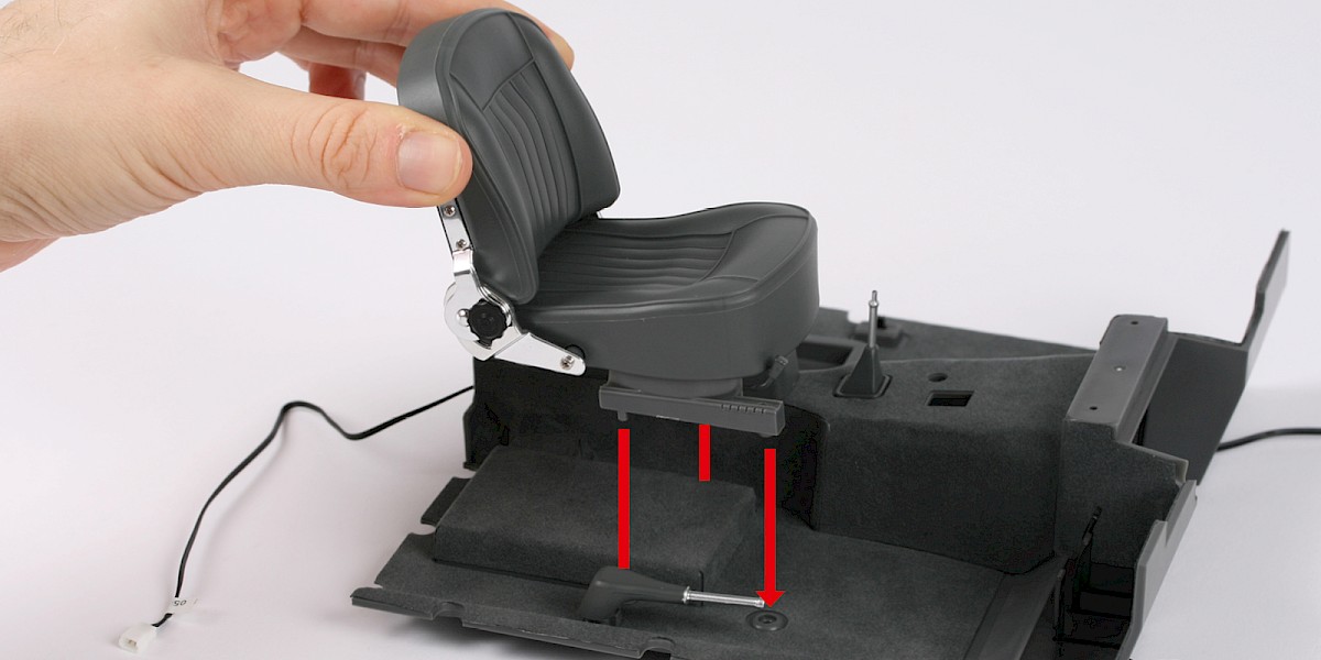
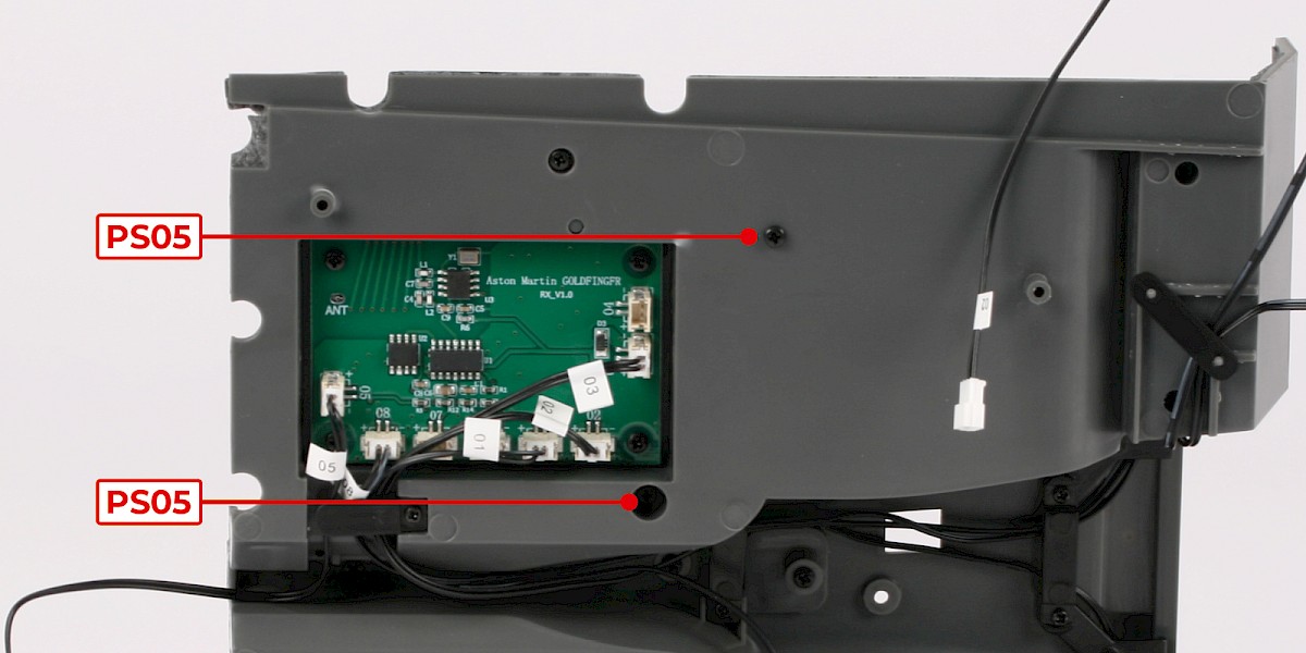
Step 12
Secure from the other side with 2x PS05.
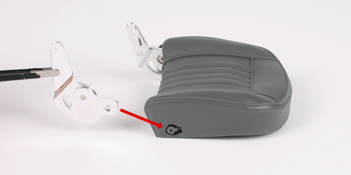
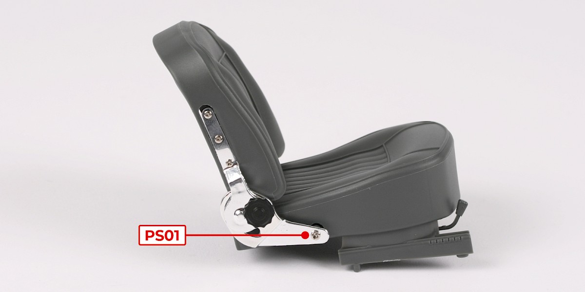
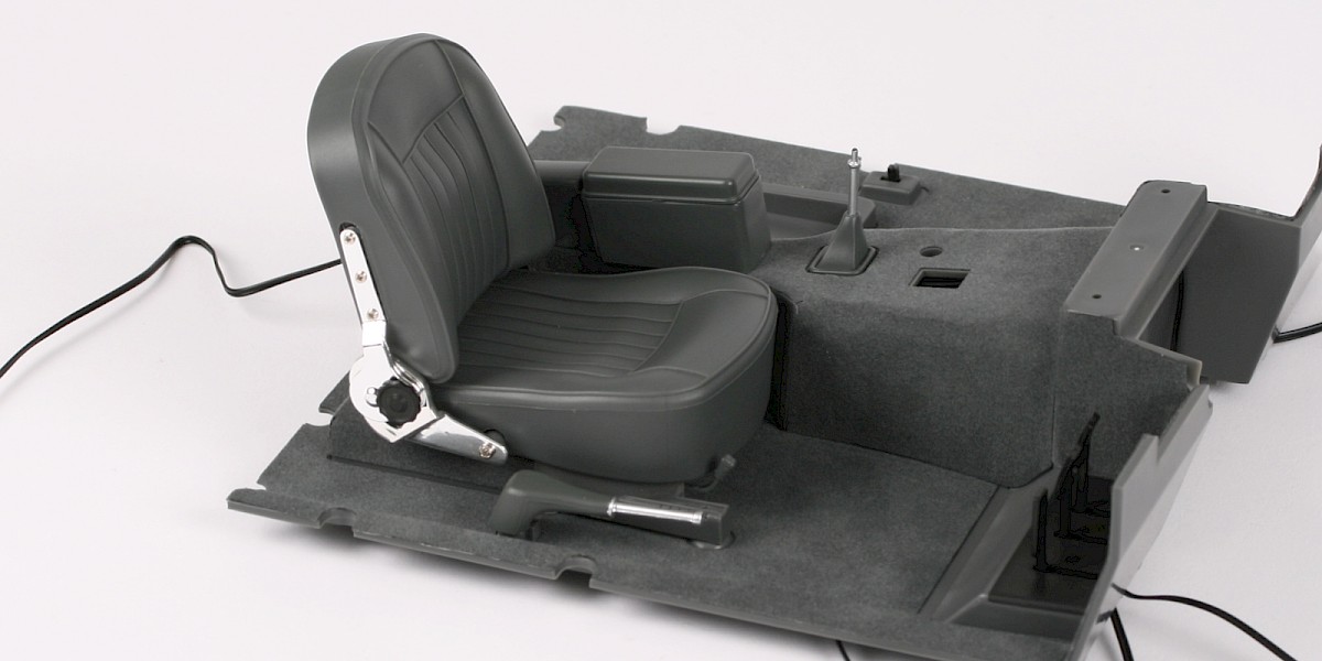
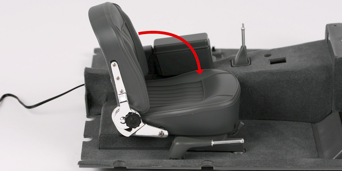
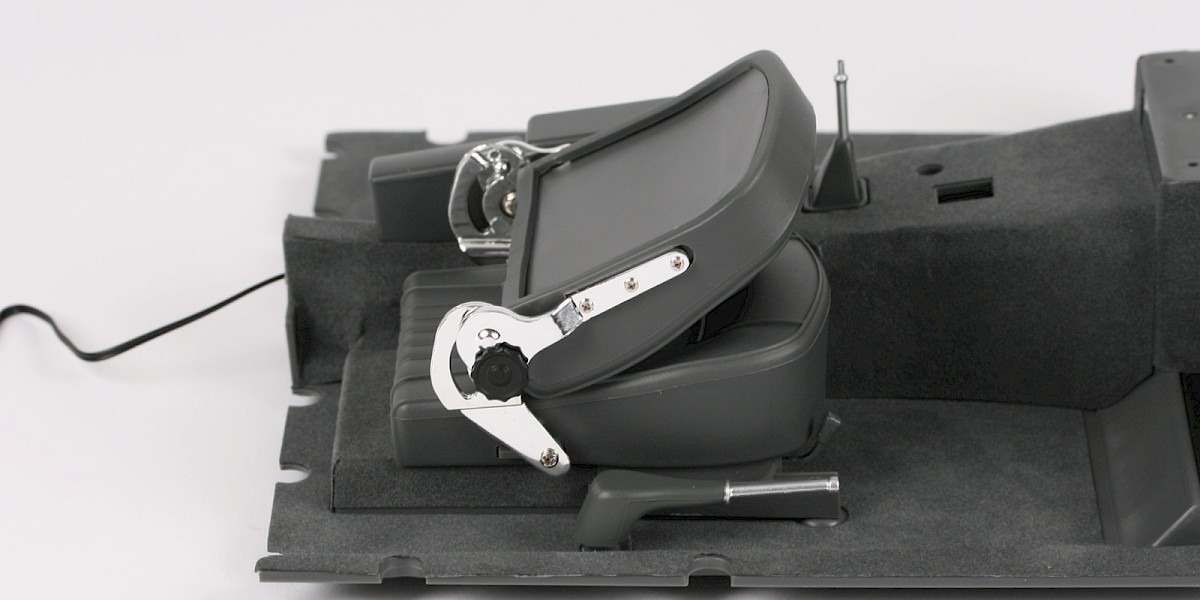
Step 13
The backrest can be adjusted forwards and backwards.
STAGE COMPLETE