
Pack 6
BUILD INSTRUCTIONS
Advice from the experts
Spare screws are included with each part. Occasionally, you may be instructed to keep spare or unused screws for a later stage. Keep these spares in a safe place and label them correctly.
Please make sure you don’t mix up the screws. They look quite similar, but the threads do vary slightly. Using the wrong screws may damage the parts. Only use the correct size screwdriver that fits the screw head firmly.
When securing parts together using multiple screws, fit each screw loosely to ensure all the parts are correctly aligned before gently tightening them firmly, but not overtight, in the order in which you placed them.
The screwdriver can be magnetized by stroking it with a magnet (fridge magnet, etc.) enabling it to hold the screws and make assembly easier.
If a screw is tight going into a metal part, do not force it as you may shear the head off. Remove it and put a tiny smear of Vaseline, soap or light oil on the thread. That will lubricate it and make it easier to tighten.
Some parts will require a little glue for assembly. Please apply glue sparingly and use a cocktail stick so that you don’t use too much nor apply the glue too heavily. We recommend superglue gel or Extra Thin Liquid modeling glue. Where possible, parts should be test-fitted in place before gluing.
Make sure you have good ventilation when using adhesives and to replace caps firmly.
Use a magnet to help find screws that have fallen on the floor.
Use masking tape to hold parts temporarily in place.
Cut parts from a sprue (framework) with side cutters or a craft knife. Side cutters tend to be easiest.
During the course of this build, you will receive many pieces that you will assemble immediately – following the instructions in the corresponding stage – and other pieces that you should store safely to one side, for use in future assembly stages.
Always protect the paint finish on components by placing a cutting mat, sheet of white paper or soft cloth on your work surface.
When plugging cables in, ensure the power is switched off. Tweezers can be used to fit the PVC cables by gripping carefully around 5mm from the end of the cable. If a cable needs to be removed from a socket, do not pull on the cable as this could damage the connection. Grip the plug with tweezers to remove it.
Left and Right! When building your AH-64 Apache, the left- or right-hand side refers to that side as if you are sitting in the cockpit.
![]() When you see this symbol, pay attention to the instruction text in bold and check the orientation of the parts in the image as this will be particularly important for assembly in later stages.
When you see this symbol, pay attention to the instruction text in bold and check the orientation of the parts in the image as this will be particularly important for assembly in later stages.
WARNING: Some parts are assembled using magnets. These magnets can cause serious injury if they are swallowed. Keep away from children. If you suspect a magnet has been swallowed, seek medical help straight away.
This is not a toy. Not suitable for children under 14 years old due to small parts. Adult supervision required.
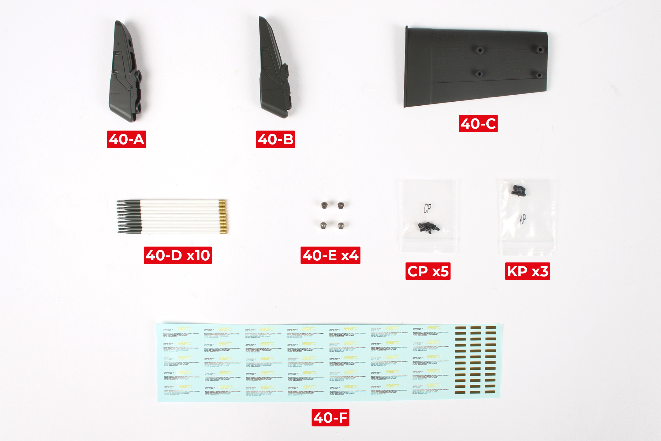
PARTS LIST
| 40-A | 40-E x4 |
| 40-B | 40-F |
| 40-C | CP x5 |
| 40-D x10 | KP x3 |
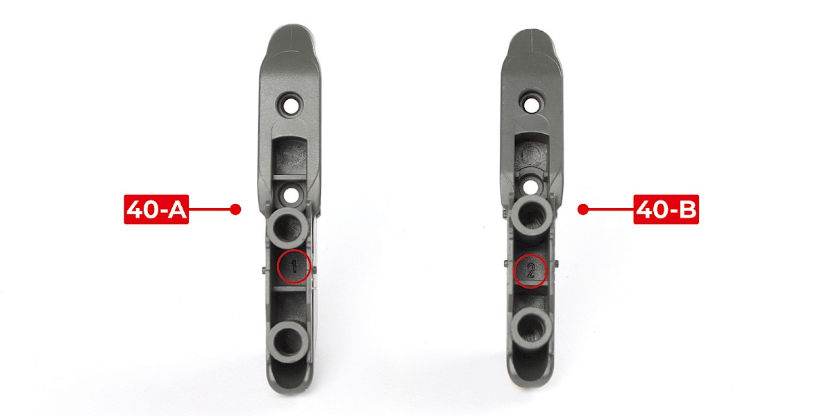
Step 1
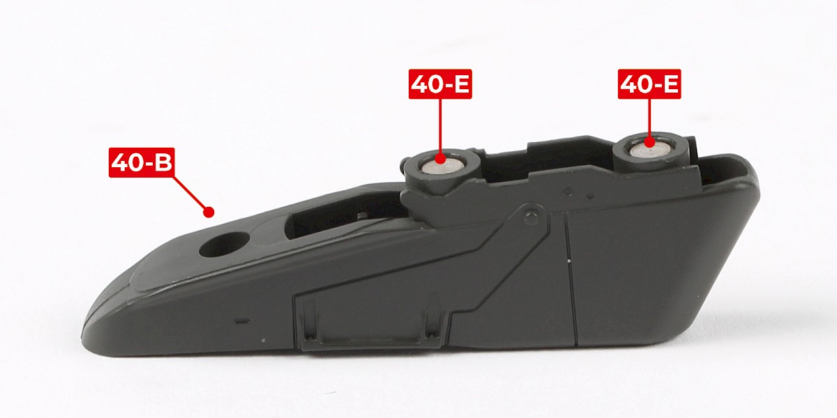
40-A and 40-B are marked '1' and '2' (circled).
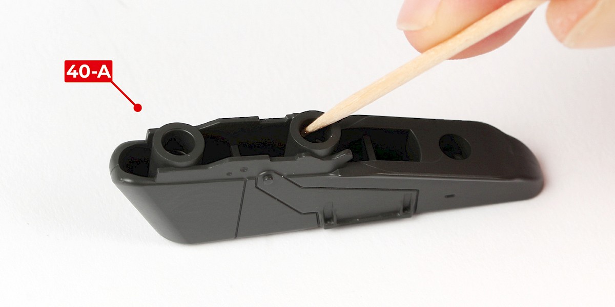
Add glue to 40-A as shown.
Step 2
Glue 40-E into 40-A.
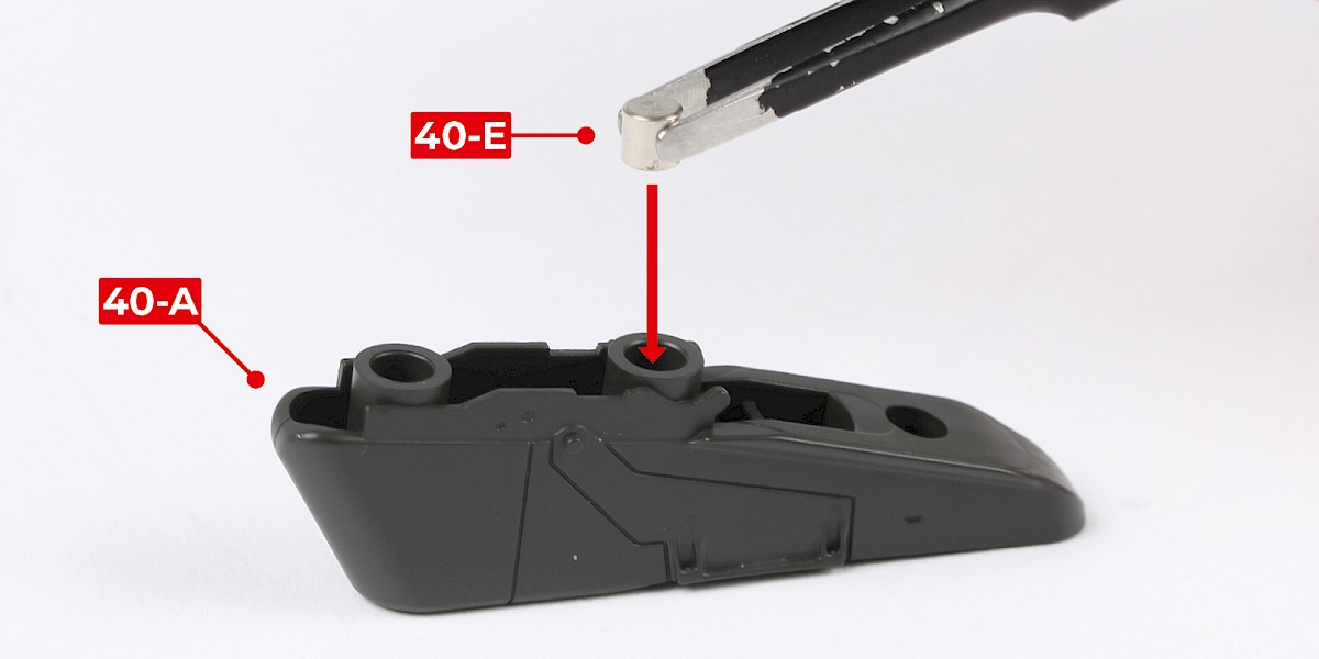
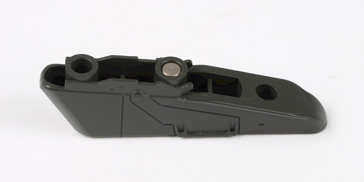
Step 3
Glue a second 40-E into 40-A.
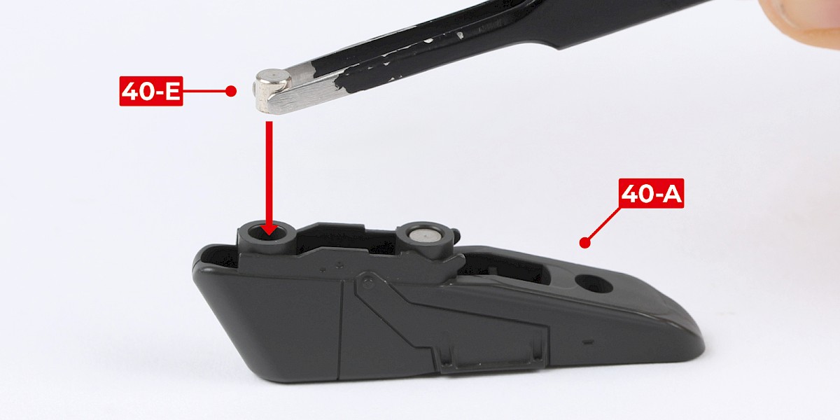
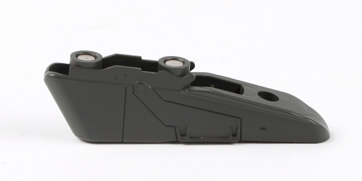
Step 4
Repeat this process to glue 2x 40-E into 40-B.

Step 5
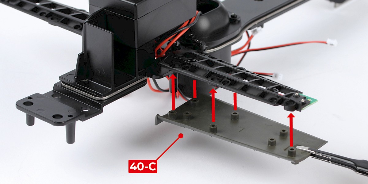
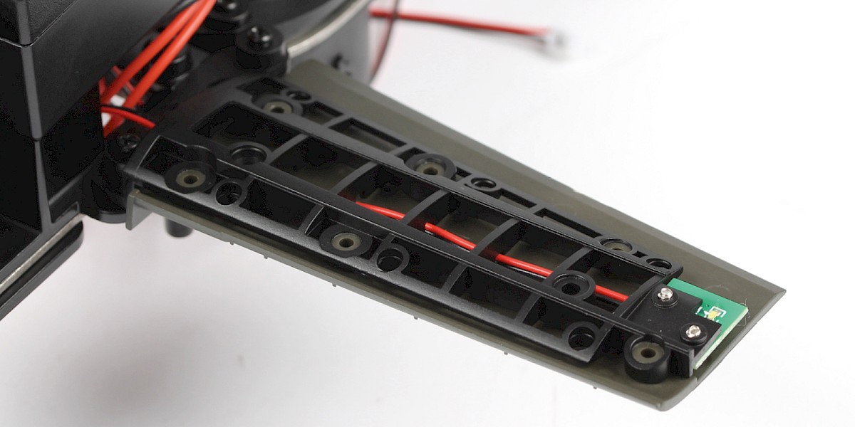
Fit 40-C to the left wing (stage 38).
Step 6
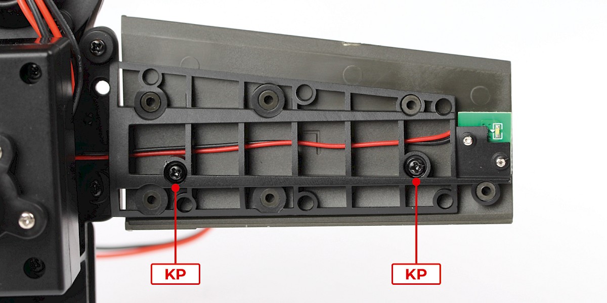
Screw in place with 2x KP.
Step 7
Cut the decals outlined in red from 40-F.

Step 8
Take 40-D and a set of decals.
Apply decals A, B, C and D to 40-D.

Step 9
Repeat step 8 to make 10 rockets.

STAGE COMPLETE
PARTS LIST
| 41-A | 41-E |
| 41-B | 41-F x2 |
| 41-C | 41-G x4 |
| 41-D x2 |
Step 1
Parts 41-F are the missiles. Take care not to damage the fragile fins on each end.
Parts 41-G are stands to be used for displaying the missiles.

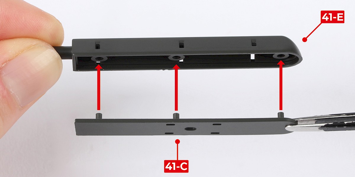
Step 2
Fit 41-C to 41-E.

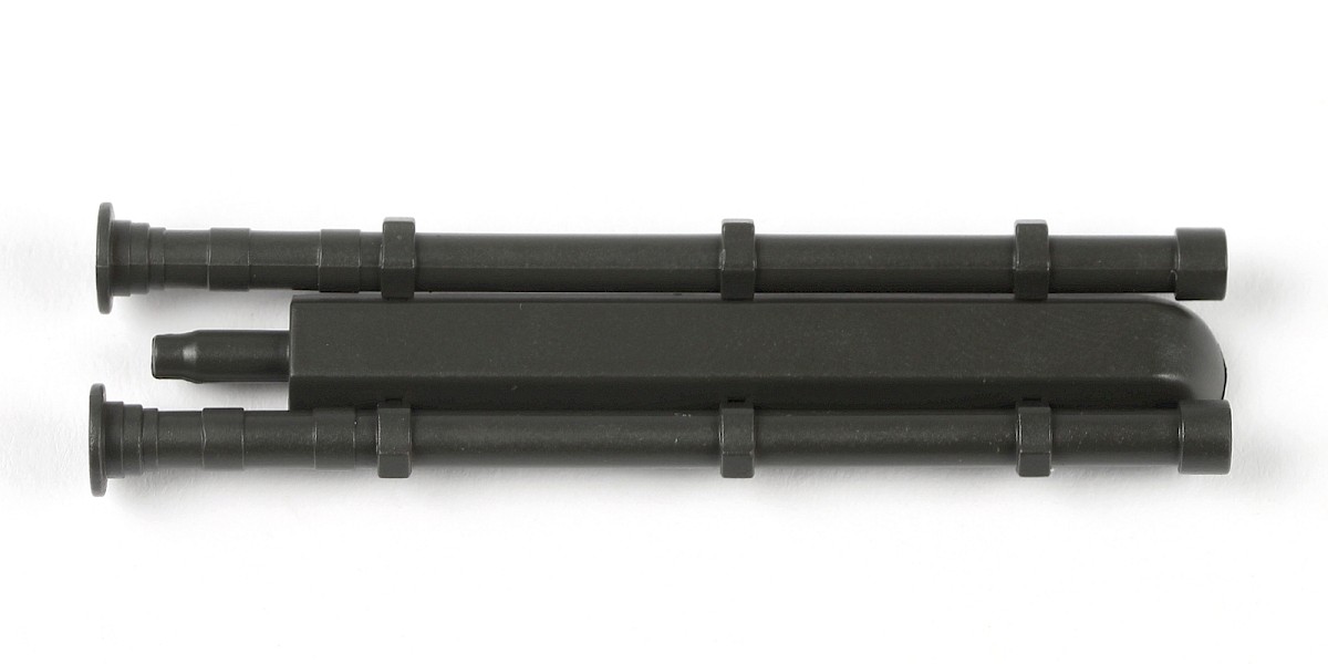
Step 3
Glue 41-D to the assembly.

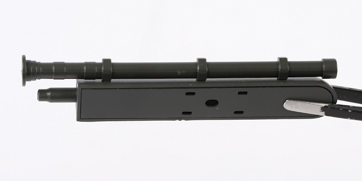
Step 4
Glue the second 41-D to the other side.

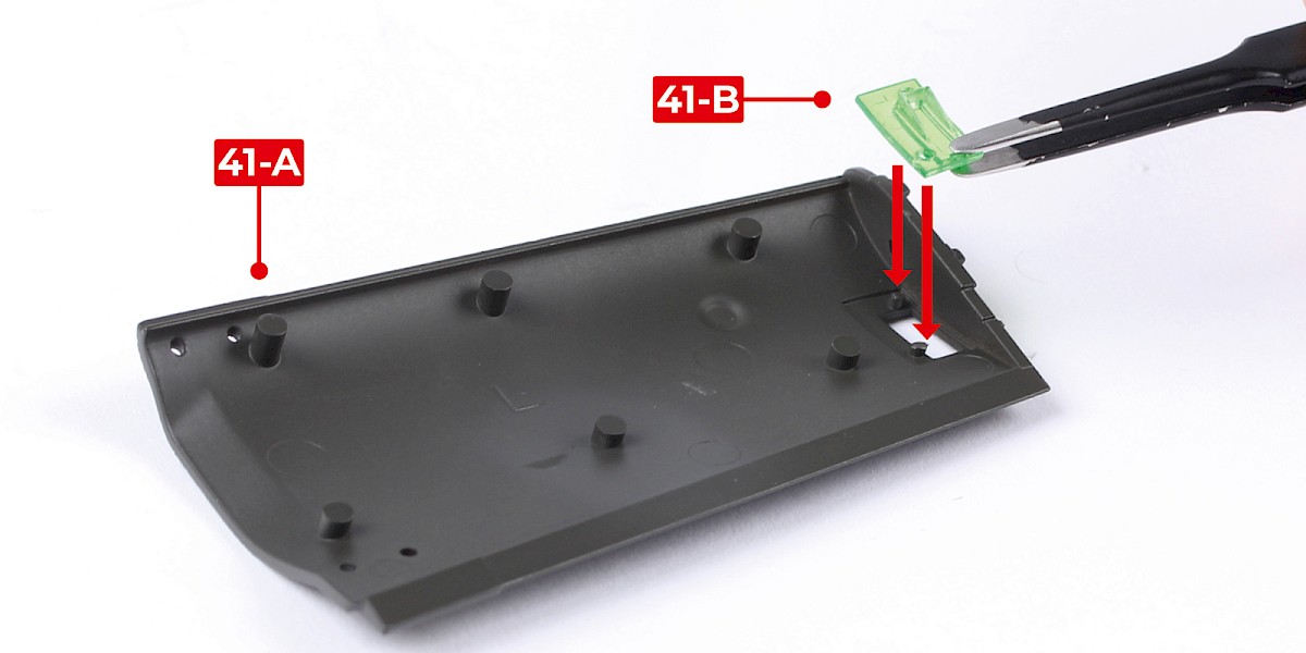
Step 5
Press 41-B into 41-A.
Step 6
Fit 41-A to the left wing (stage 040).
STAGE COMPLETE
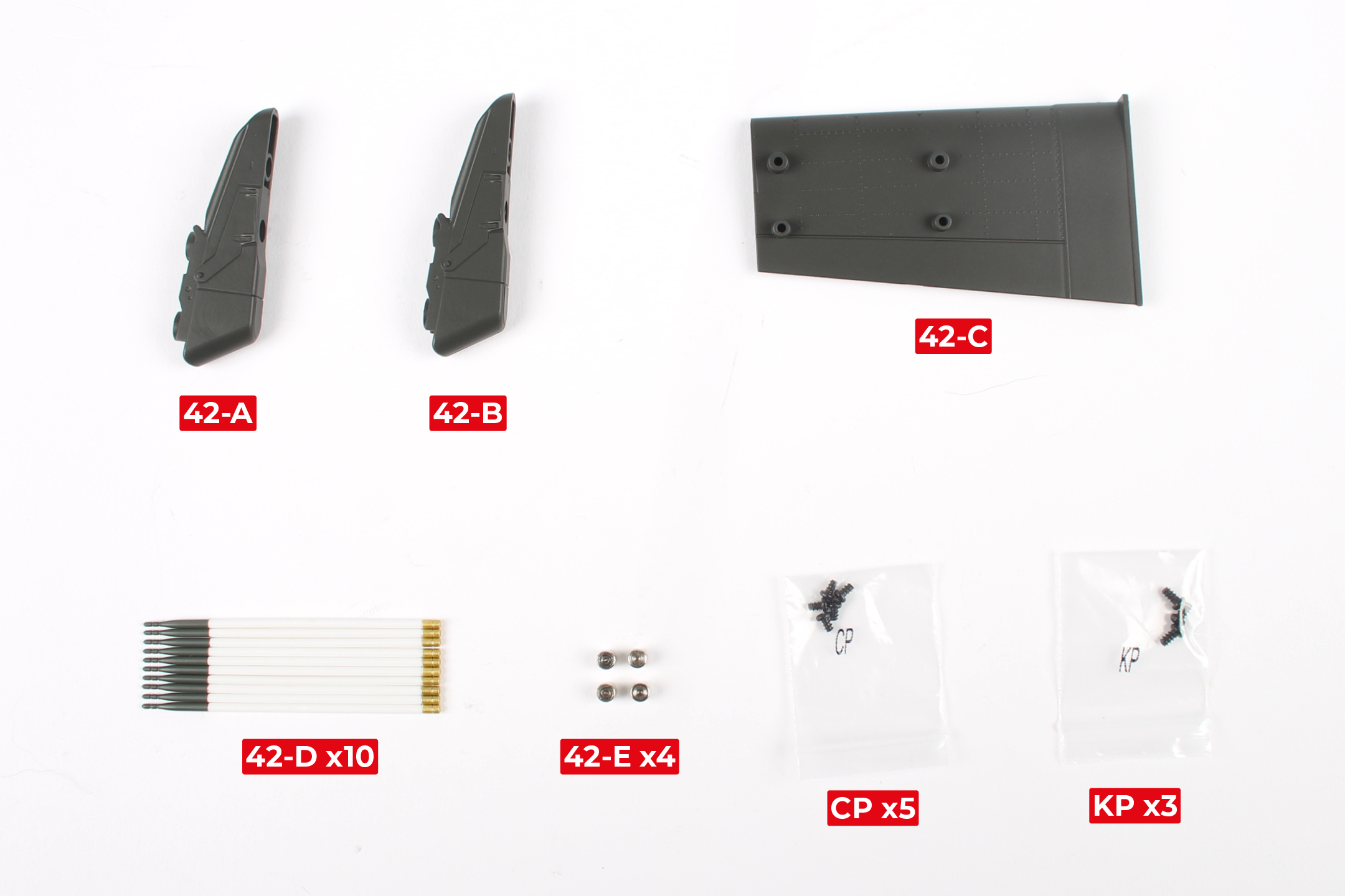
PARTS LIST
| 42-A | 42-E x4 |
| 42-B | CP x5 |
| 42-C | KP x3 |
| 42-D x10 |
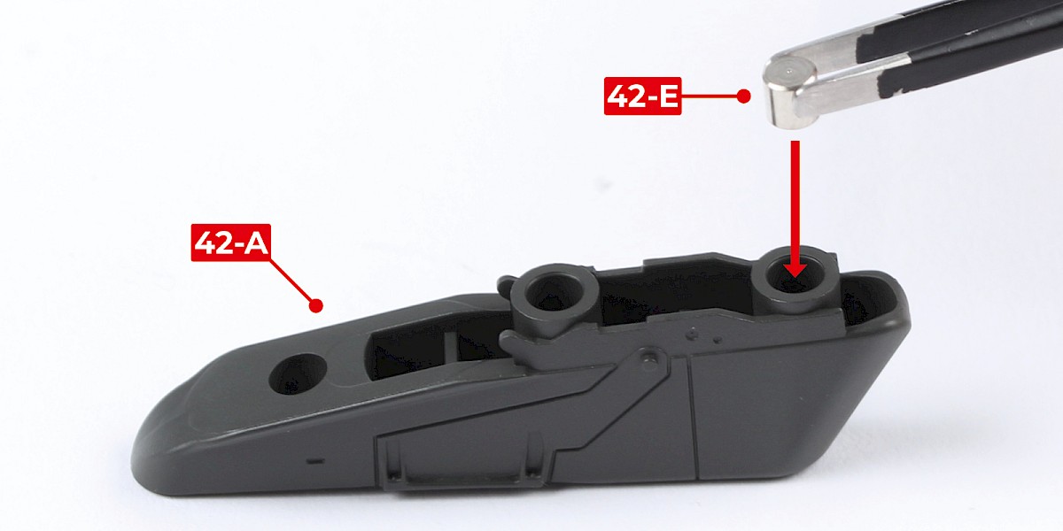
Step 1
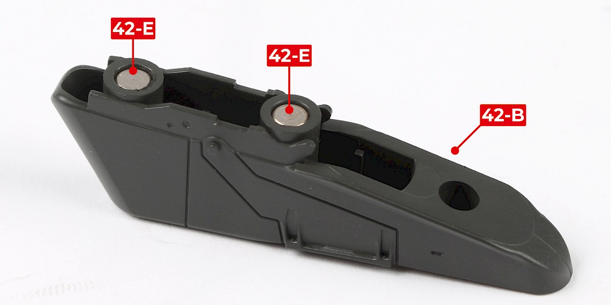
42-A and 42-B are marked '1' and '2' (circled).

Step 2
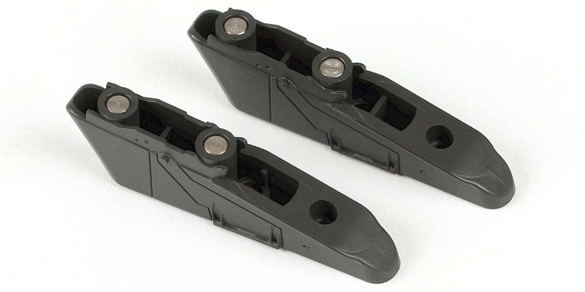
Glue 42-E into 42-A.
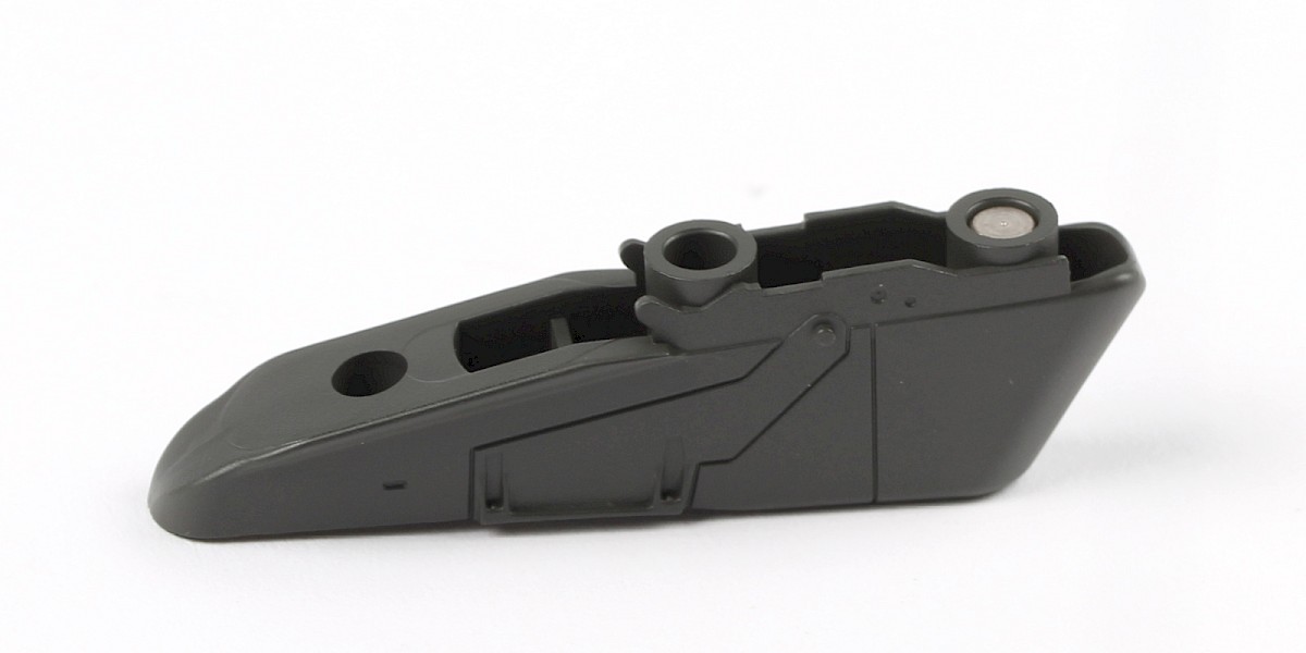
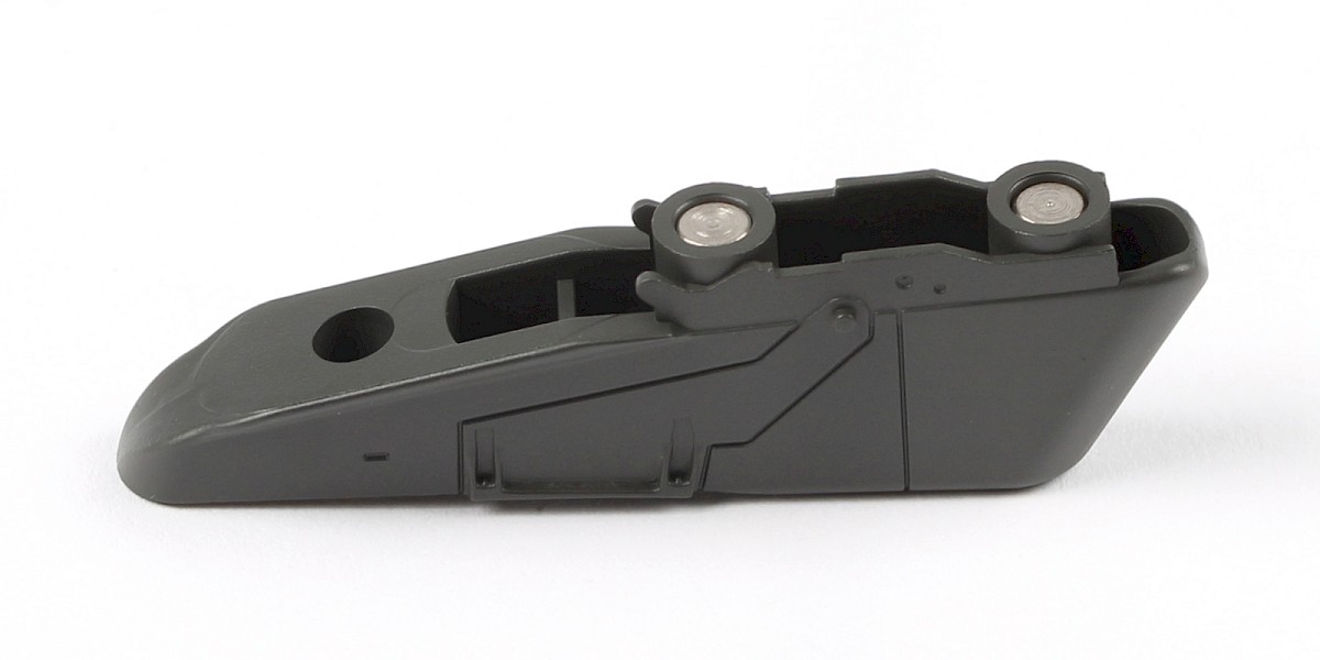
Step 3
Glue a second 42-E into 42-A.

Step 4
Repeat this process to glue 2x 42-E into 42-B.
Step 5
Fit 42-C to the right wing (stage 41).
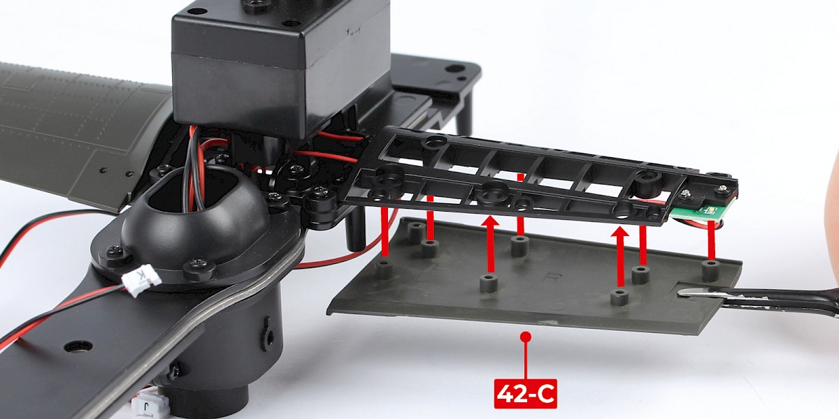
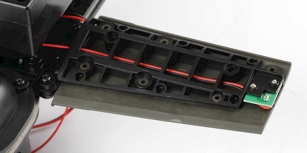
Step 6
Screw in place with 2x KP.
Step 7
Cut the decals outlined in red from 40-F.

Step 8
Take 42-D and a set of decals.
Apply decals A, B, C and D to 42-D.


Step 9
Repeat step 8 to make 10 rockets.

STAGE COMPLETE
PARTS LIST
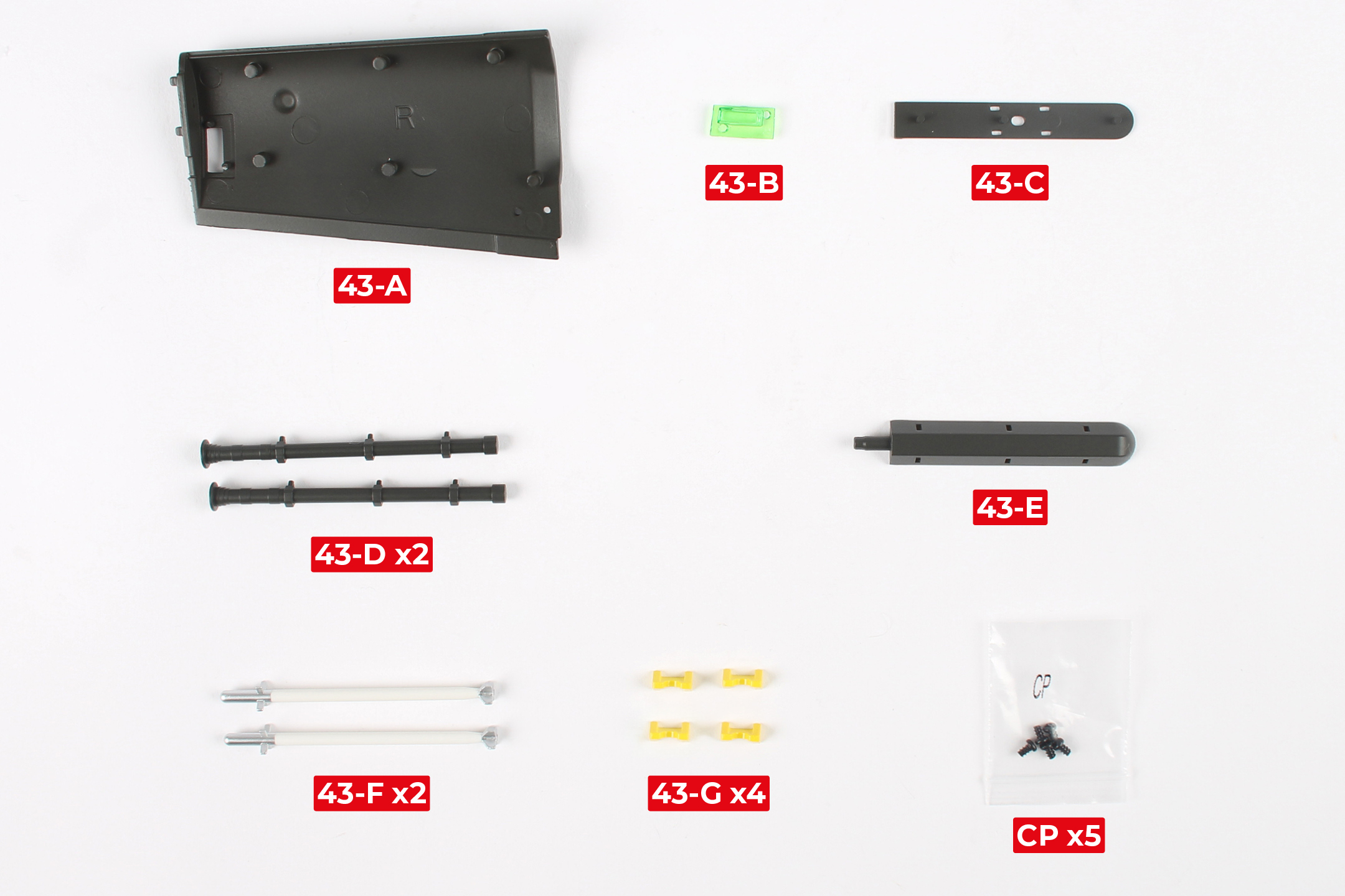
| 43-A | 43-E |
| 43-B | 43-F x2 |
| 43-C | 43-G x4 |
| 43-D x2 | CP x5 |
Step 1
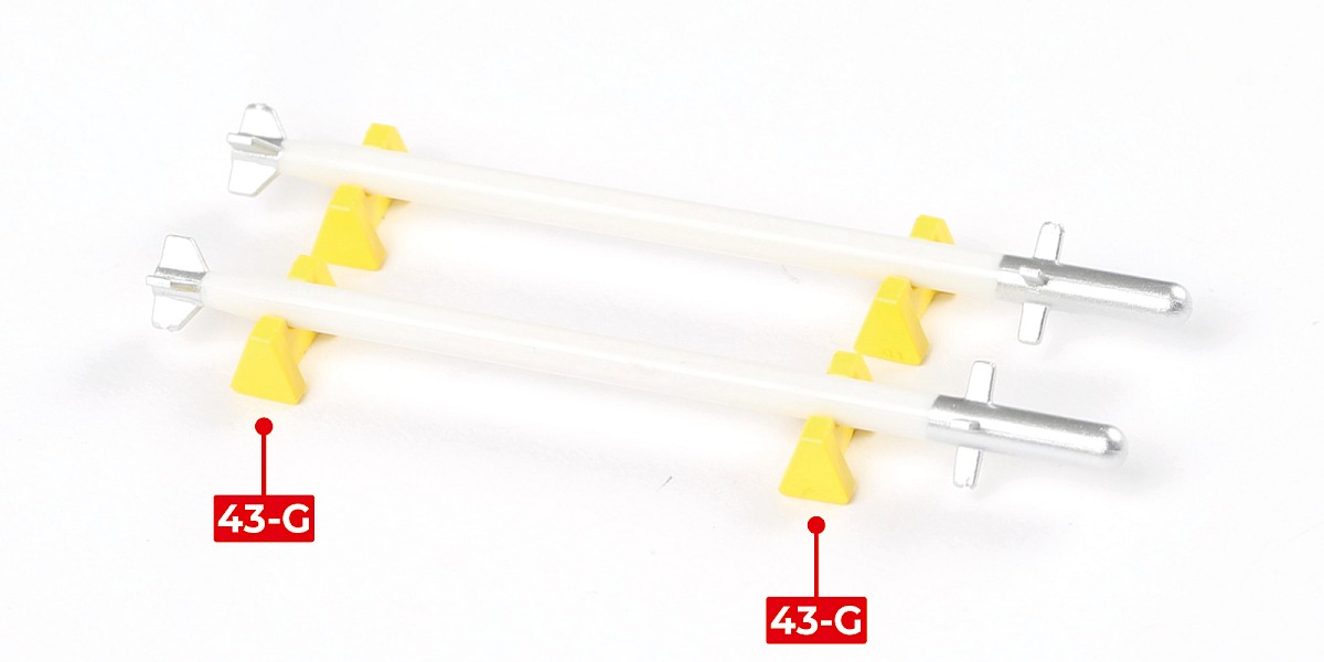
Parts 43-F are the missiles. Take care not to damage the fragile fins on each end.
Parts 43-G are stands to be used for displaying the missiles.

Step 2
Fit 43-C to 43-E.

Step 3
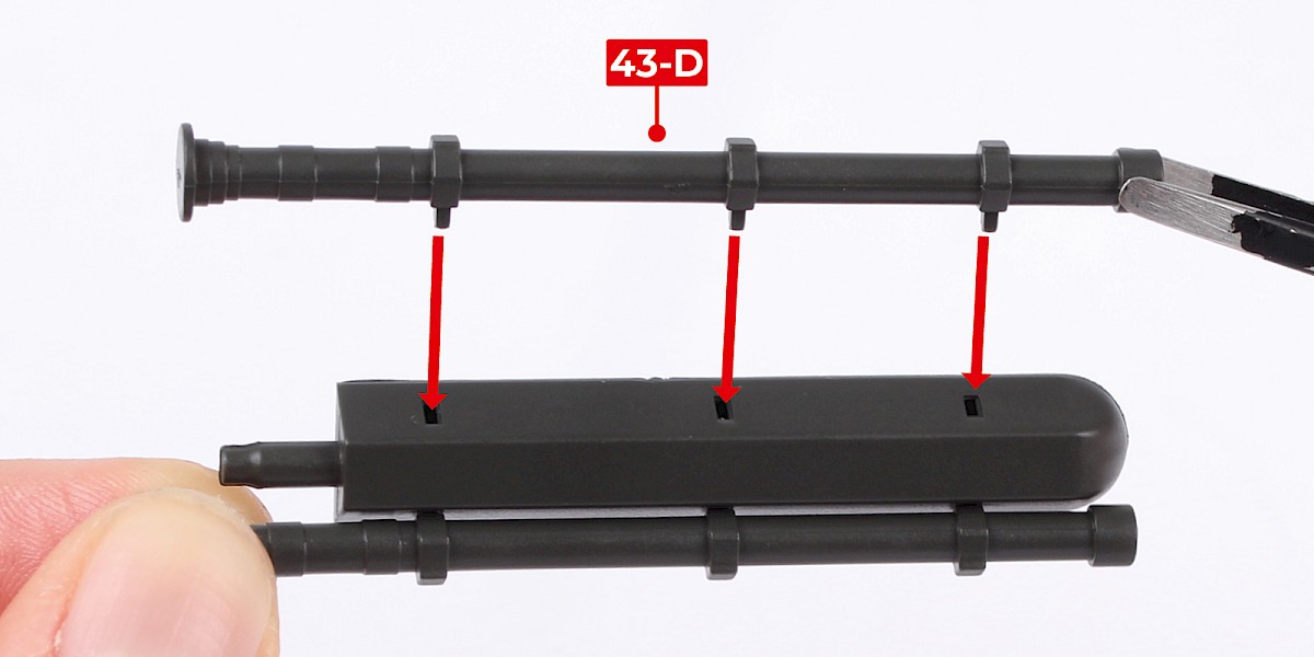
Glue 43-D to the assembly.
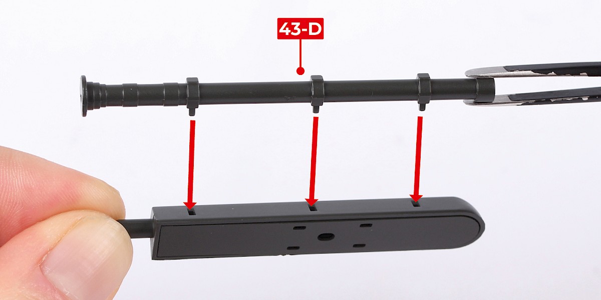

Step 4
Glue the second 43-D to the other side.

Step 5
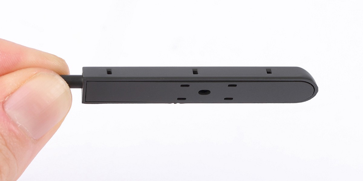
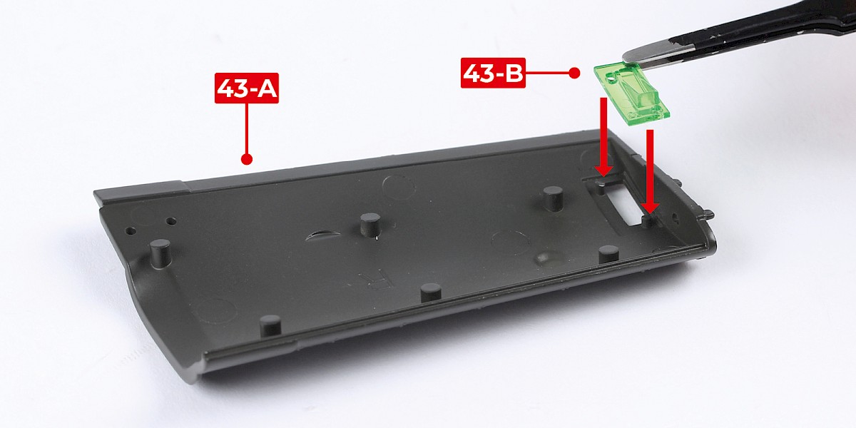
Press 43-B into 43-A.
Step 6
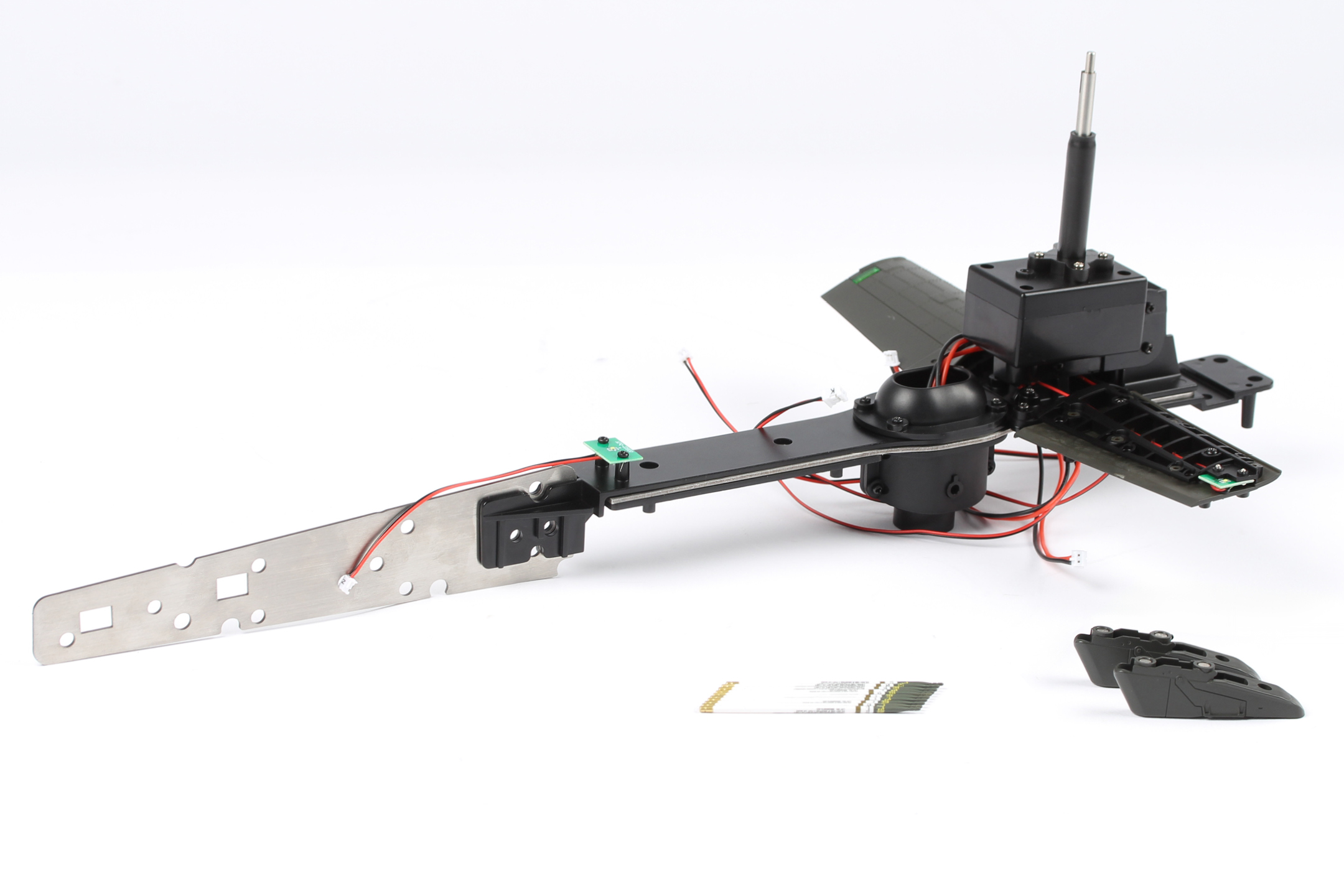
Fit 43-A to the right wing (stage 042).
STAGE COMPLETE
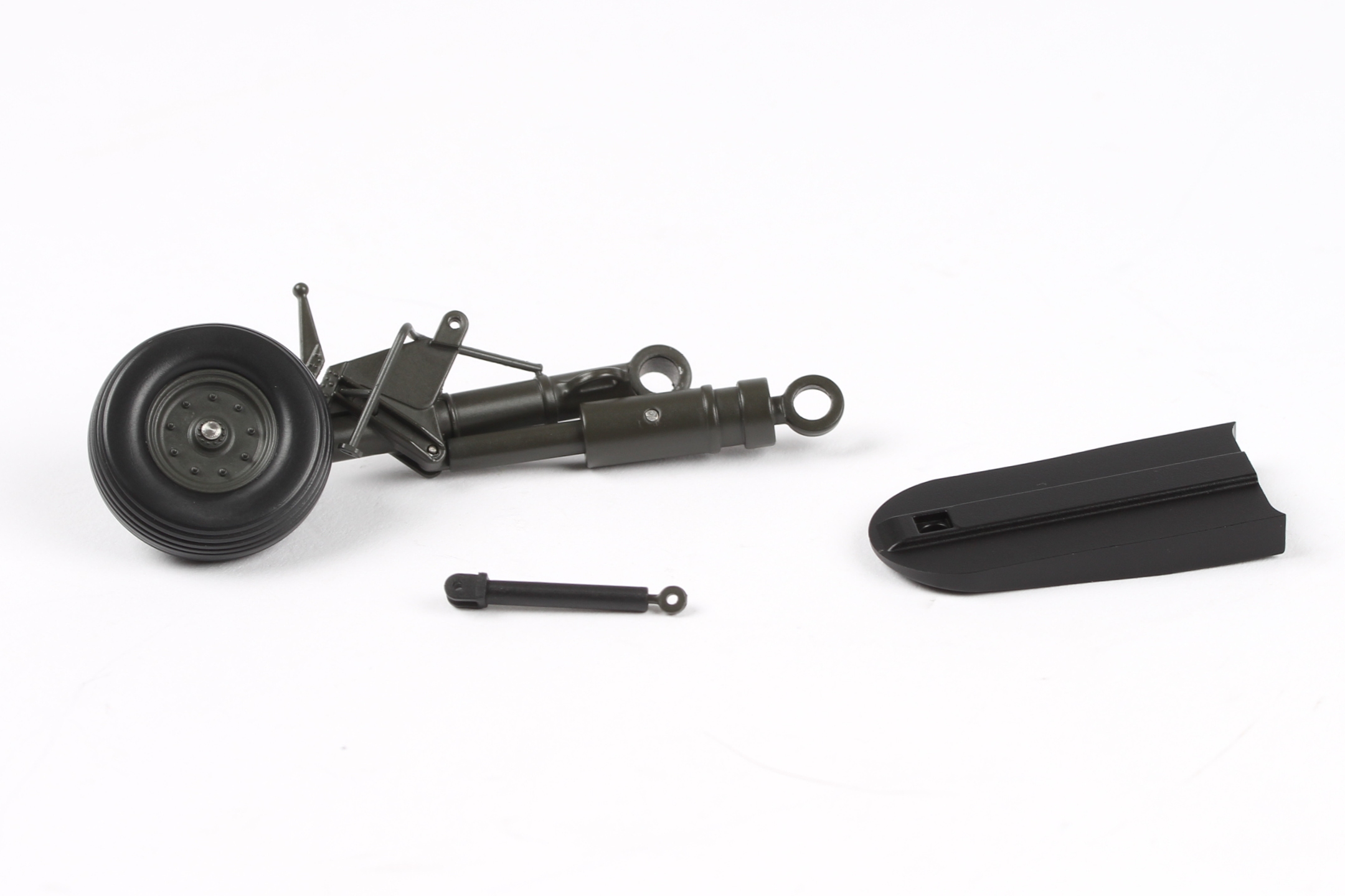
PARTS LIST
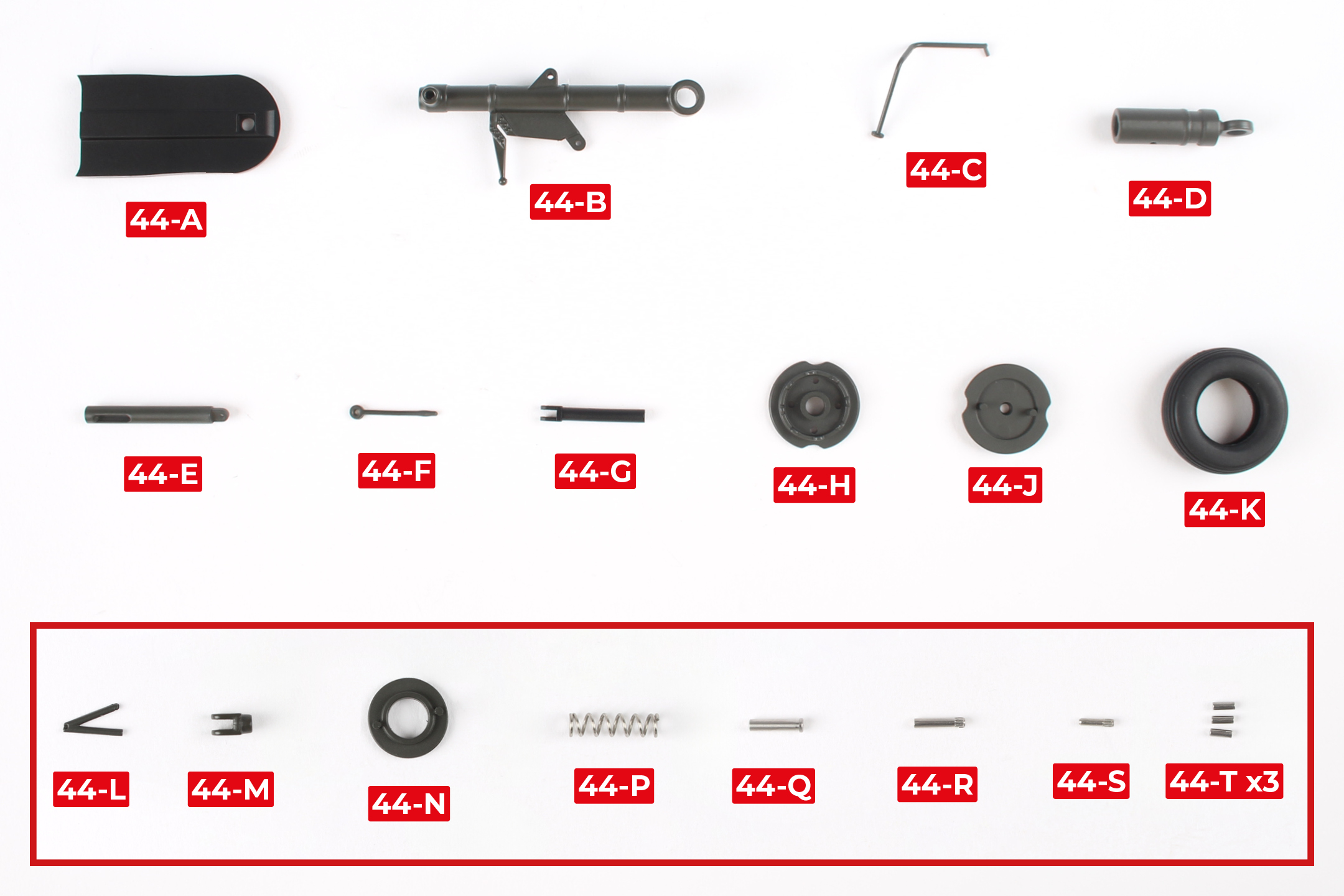
| 44-A | 44-G | 44-N |
| 44-B | 44-H | 44-P |
| 44-C | 44-J | 44-Q |
| 44-D | 44-K | 44-R |
| 44-E | 44-L | 44-S |
| 44-F | 44-M | 44-T x3 |
* The parts in bold have been magnified in the image below. Some of these parts are very small so be careful not to lose them.
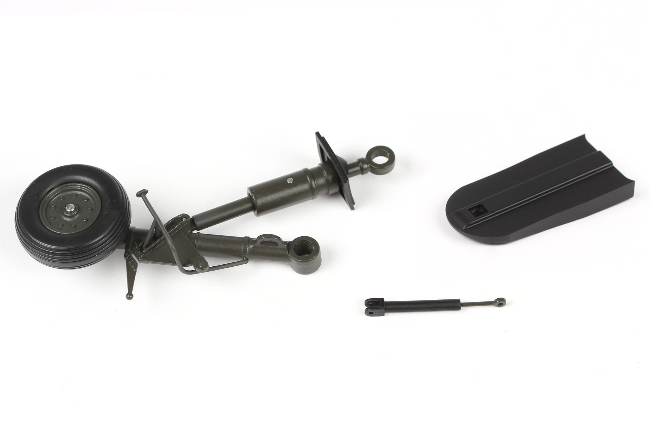
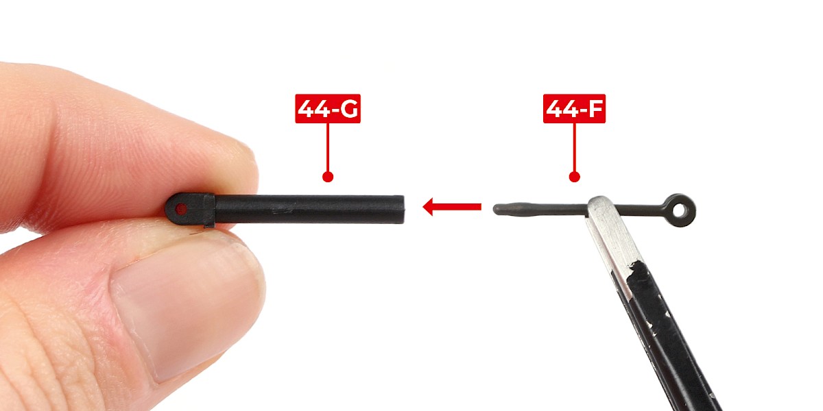
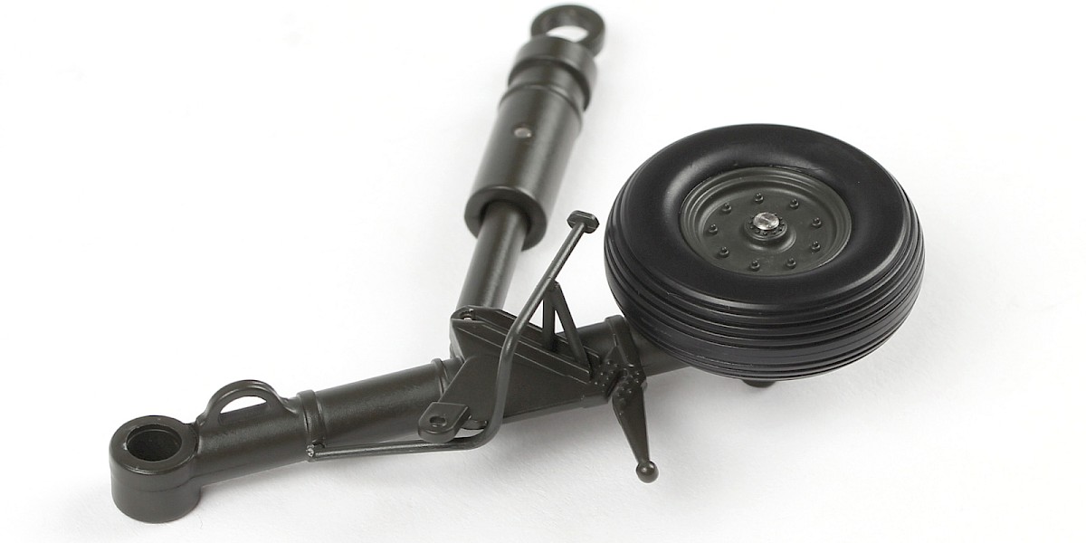
Step 1
Insert 44-F into 44-G.

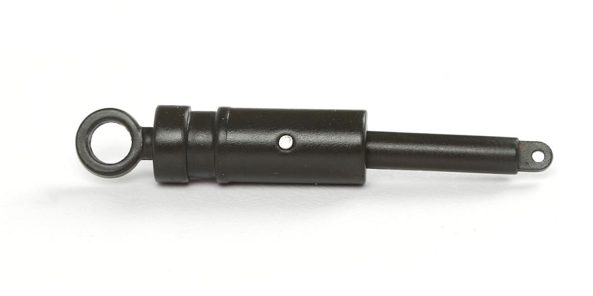
Step 2
Fit 44-P into 44-D.
Insert 44-E into 44-D.


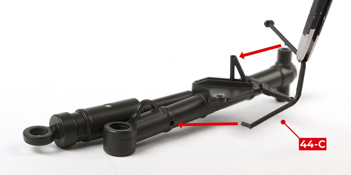
Step 3
Align 44-R with the assembly.
Compress the spring inside the assembly, then insert 44-R and use pliers to press into place. Take extra care with this step.


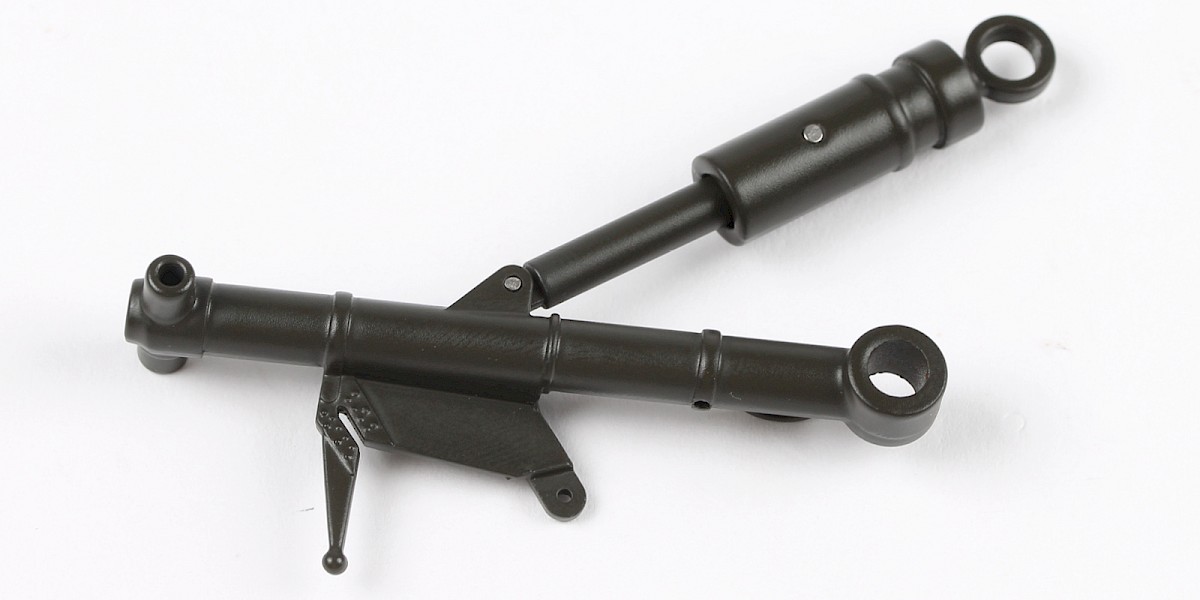
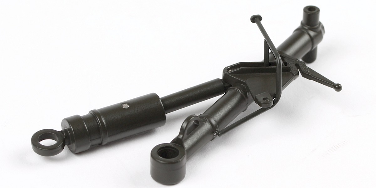
Step 4
The assembly should look like this once the parts are secured.
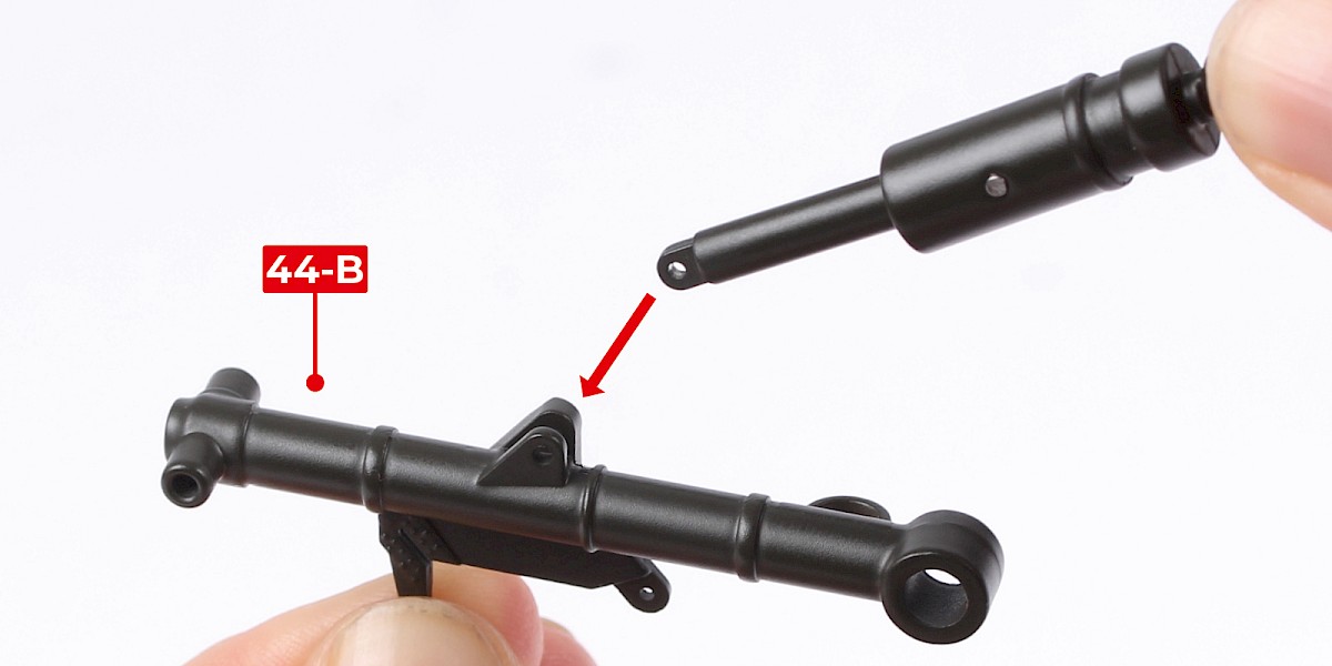
Step 5
Fit the assembly to 44-B.
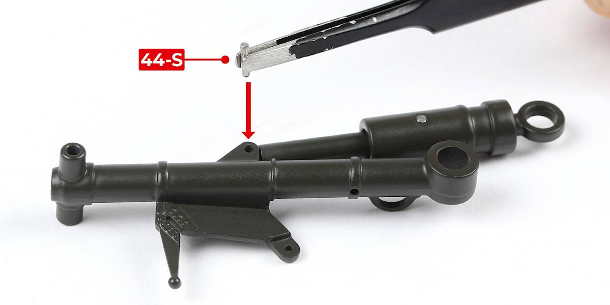
Step 6
Fix in place with 44-S, fitting the smooth end first.
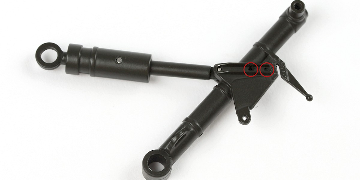
Step 7
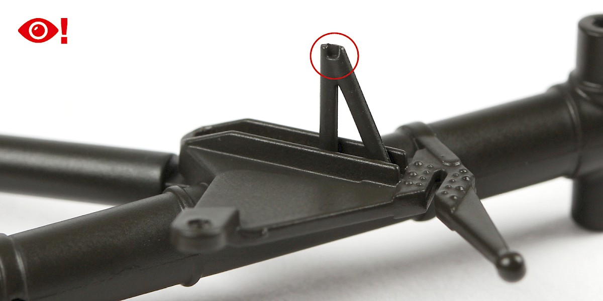
Turn the assembly over and locate the circled recesses.
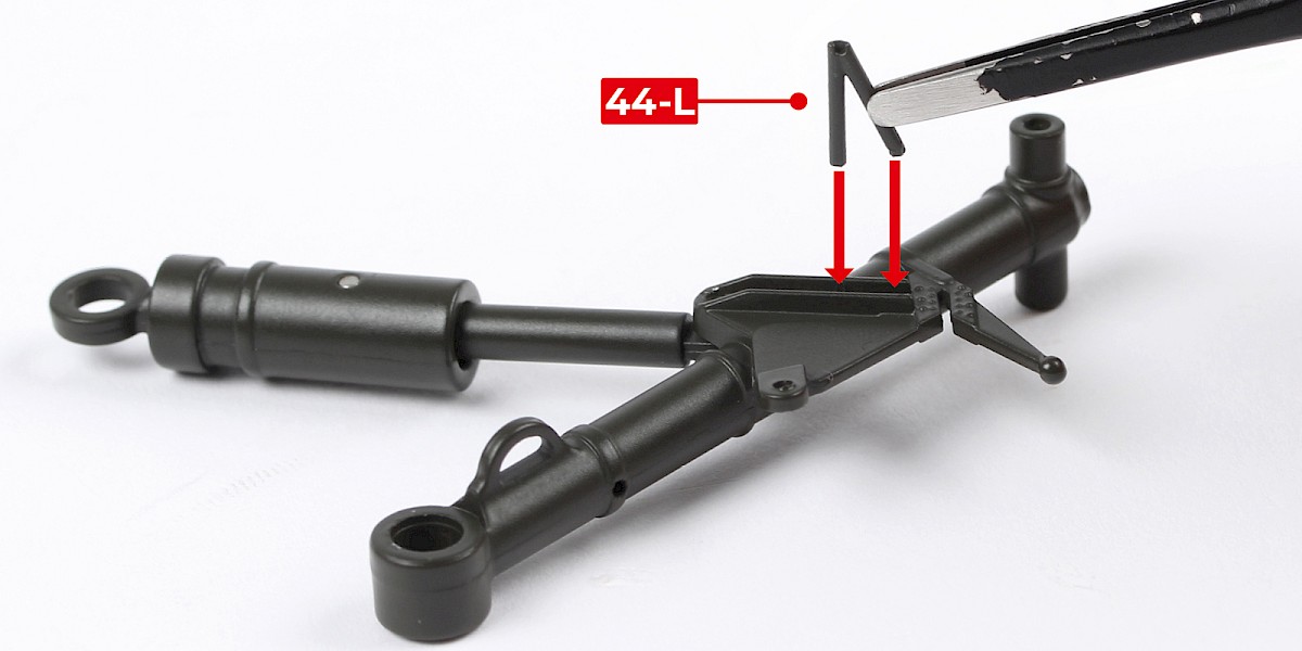
Step 8
Glue 44-L into the recesses.
Check the images carefully to orient the parts correctly.
Step 9
Glue 44-C to the assembly.
Step 10
Fit 44-J to 44-H.

Step 11
Fit 44-N into place.

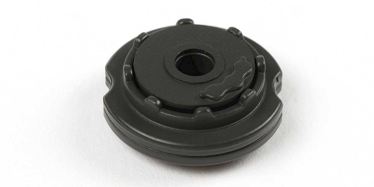
Step 12
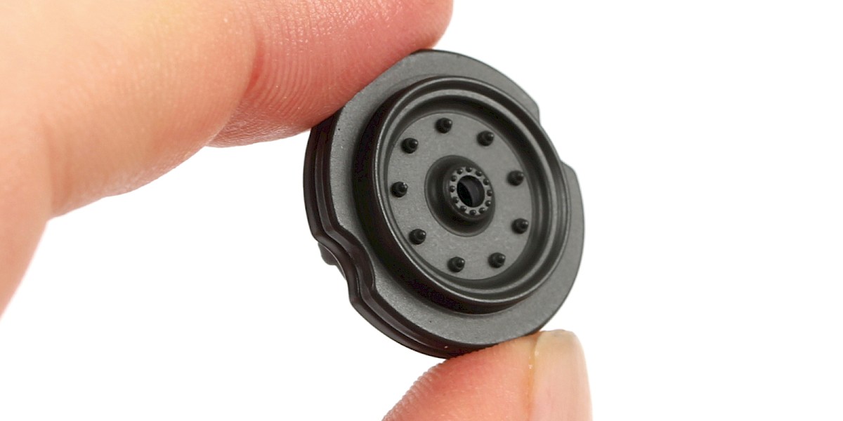
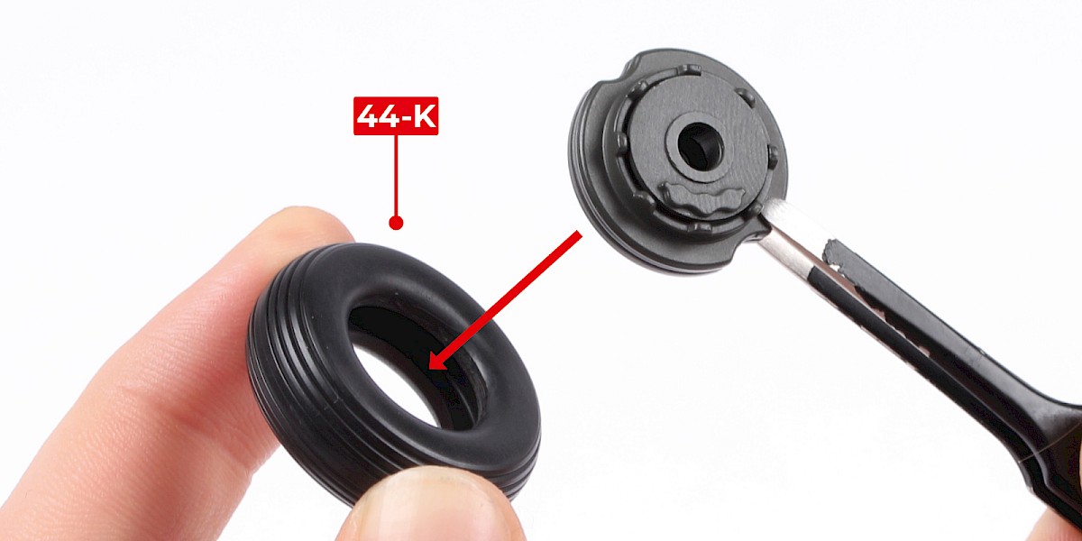
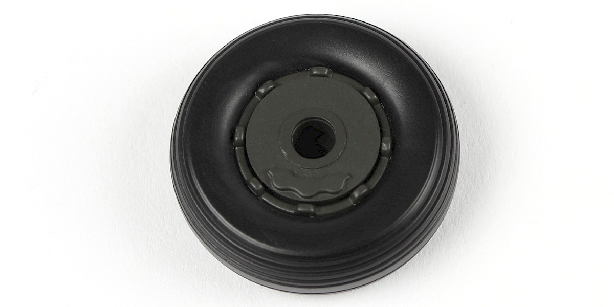
Place 44-K into hot water for 1–2 minutes to soften it.
Carefully remove 44-K from the water. Fit the wheel hub into 44-K.
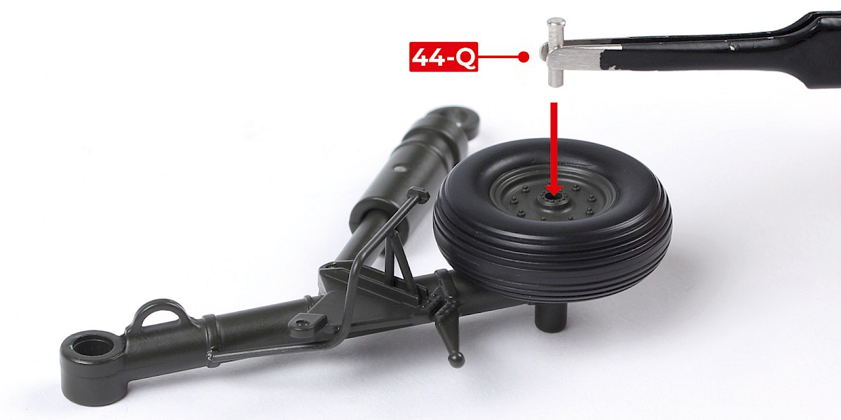
Step 13
Fit the wheel to the assembly.

Step 14
Secure with 44-Q, fitting the smooth end first.
STAGE COMPLETE
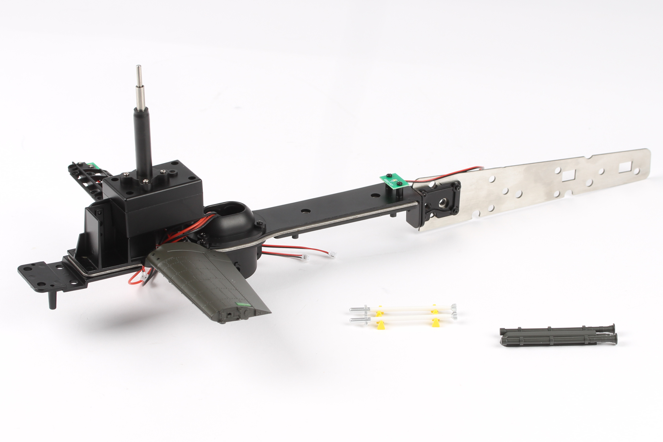
PARTS LIST
| 45-A | CM x4 |
| 45-B | DM x2 |

Step 1
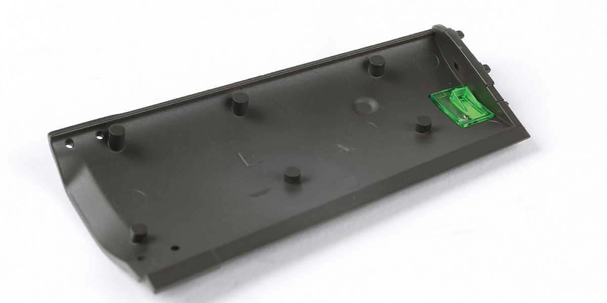
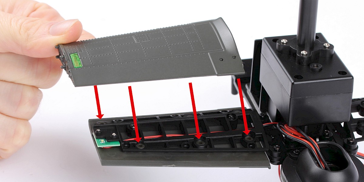
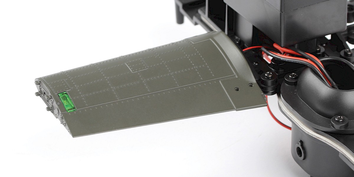
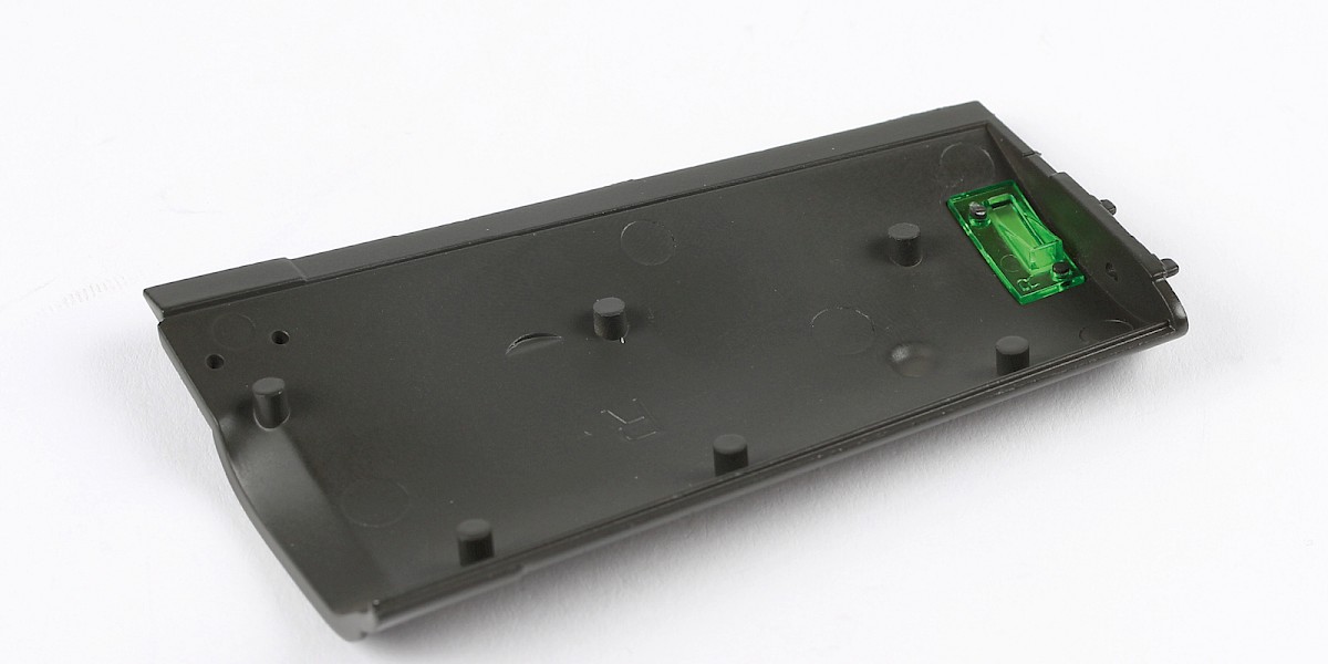
Insert 45-B into the left tail skin (stage 39).

STAGE COMPLETE
PARTS LIST
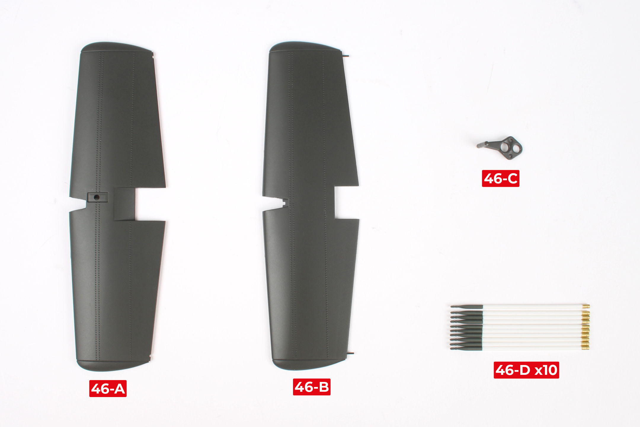
| 46-A | 46-C |
| 46-B | 46-D x10 |
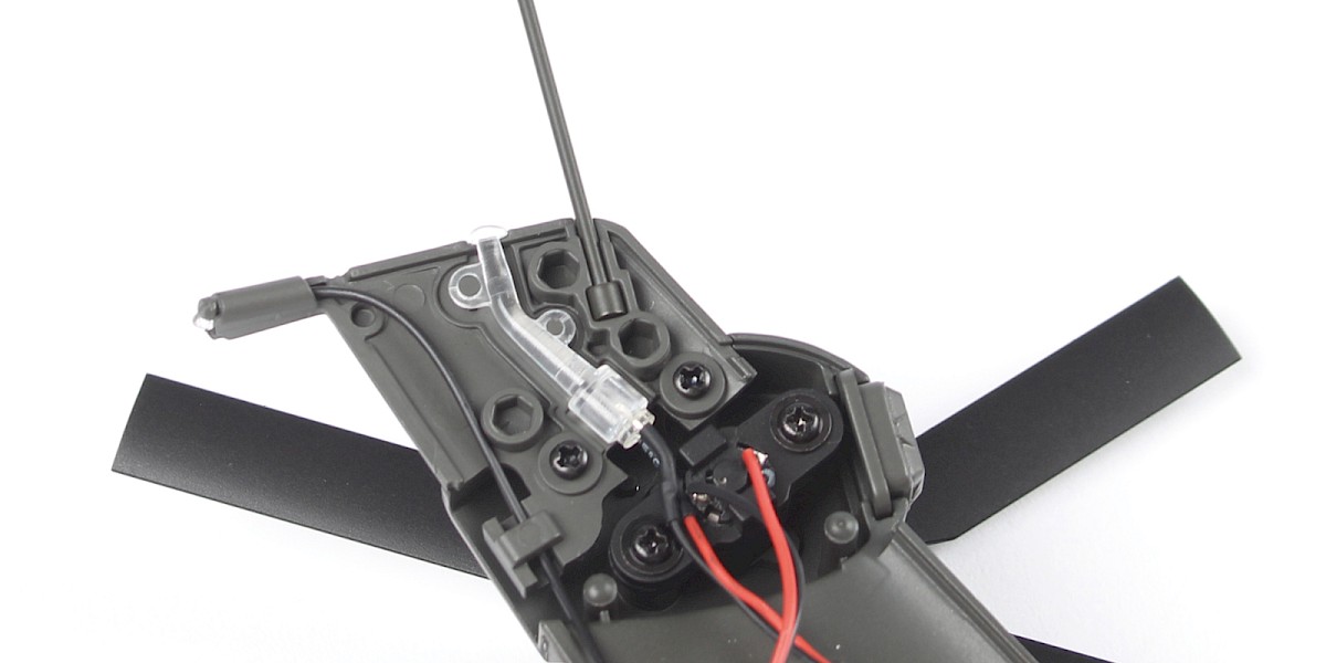
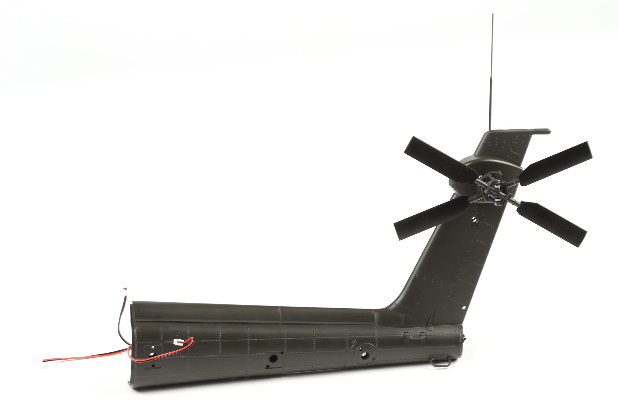
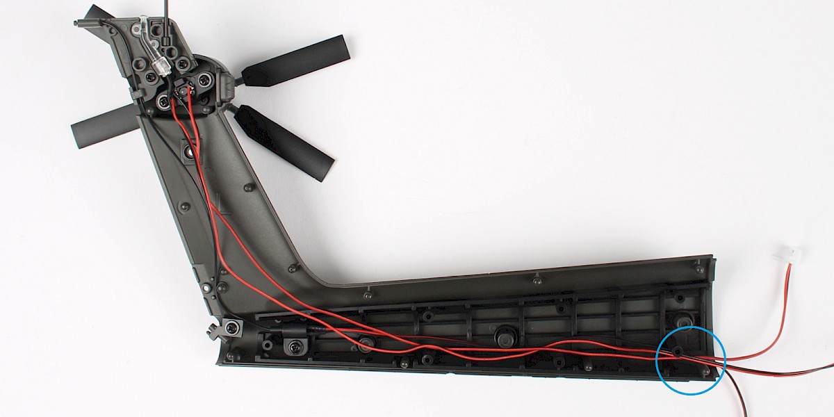
Step 1
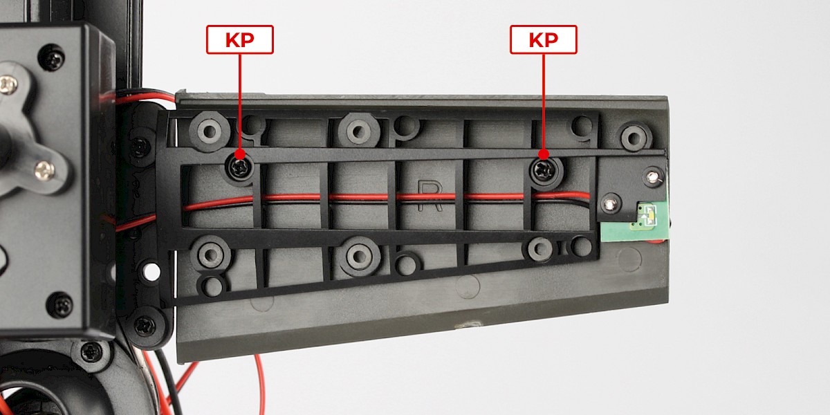
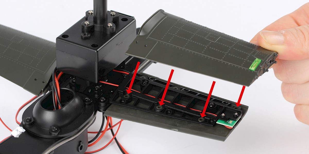
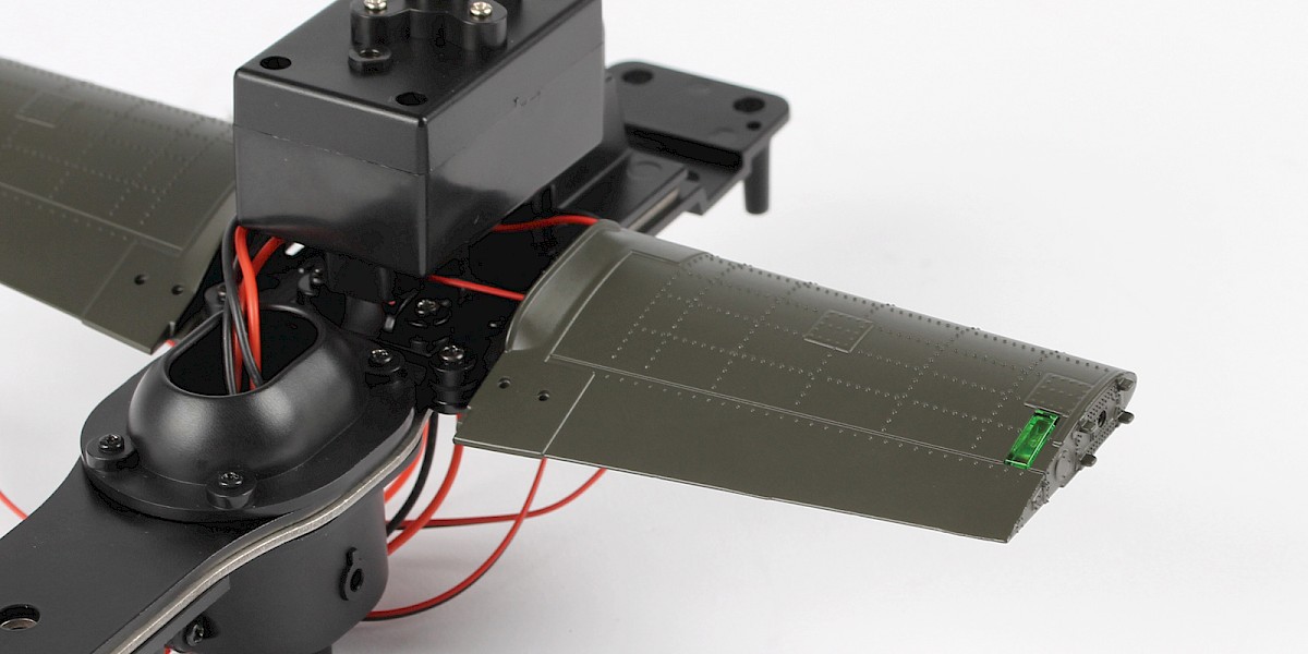
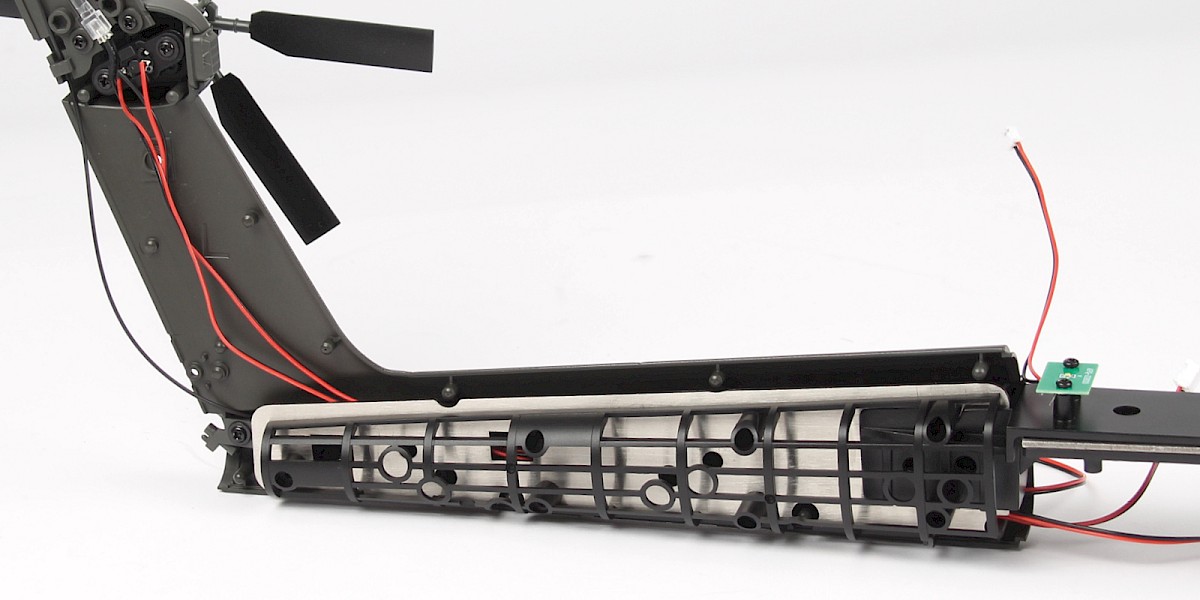
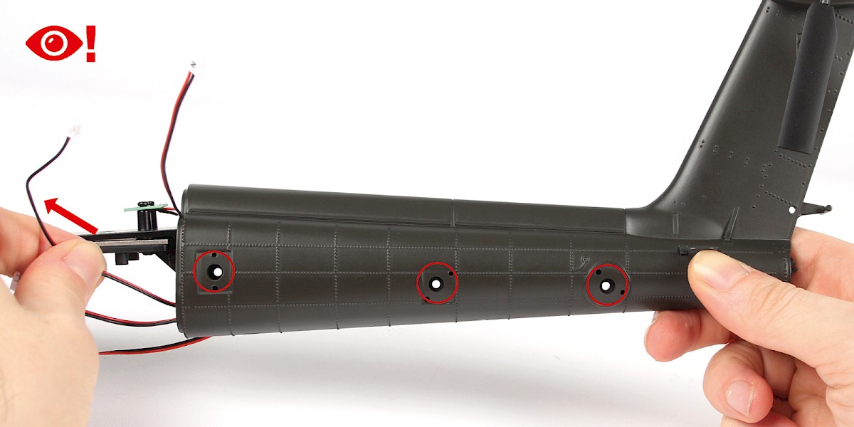
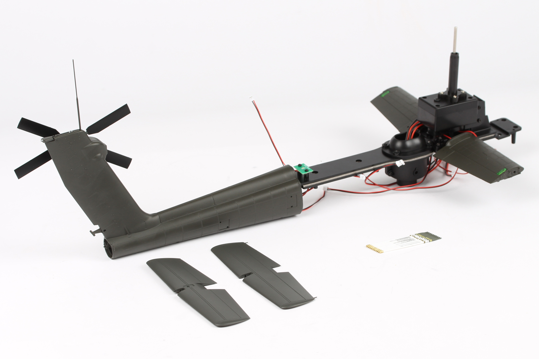
Take the left tail skin (stage 45) and arrange the cables as shown (blue circle).
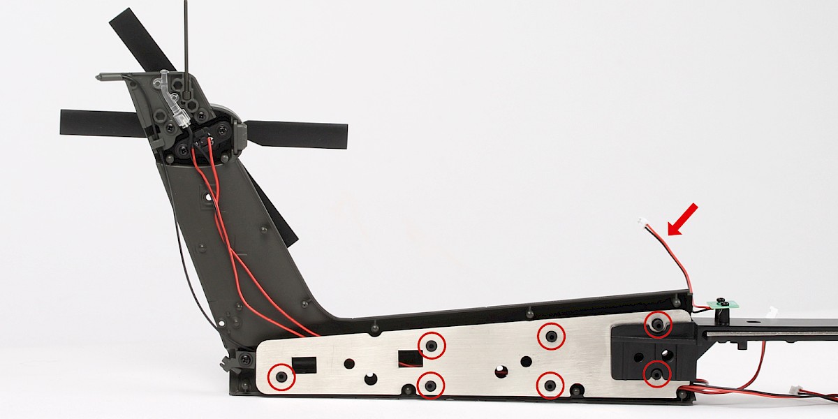
Fit the main assembly (stage 43) over the screw posts (circled). Bend the cable marked 'N' (arrow) away from the tail.
Step 2
Fit 37-B (stage 37) to the assembly.
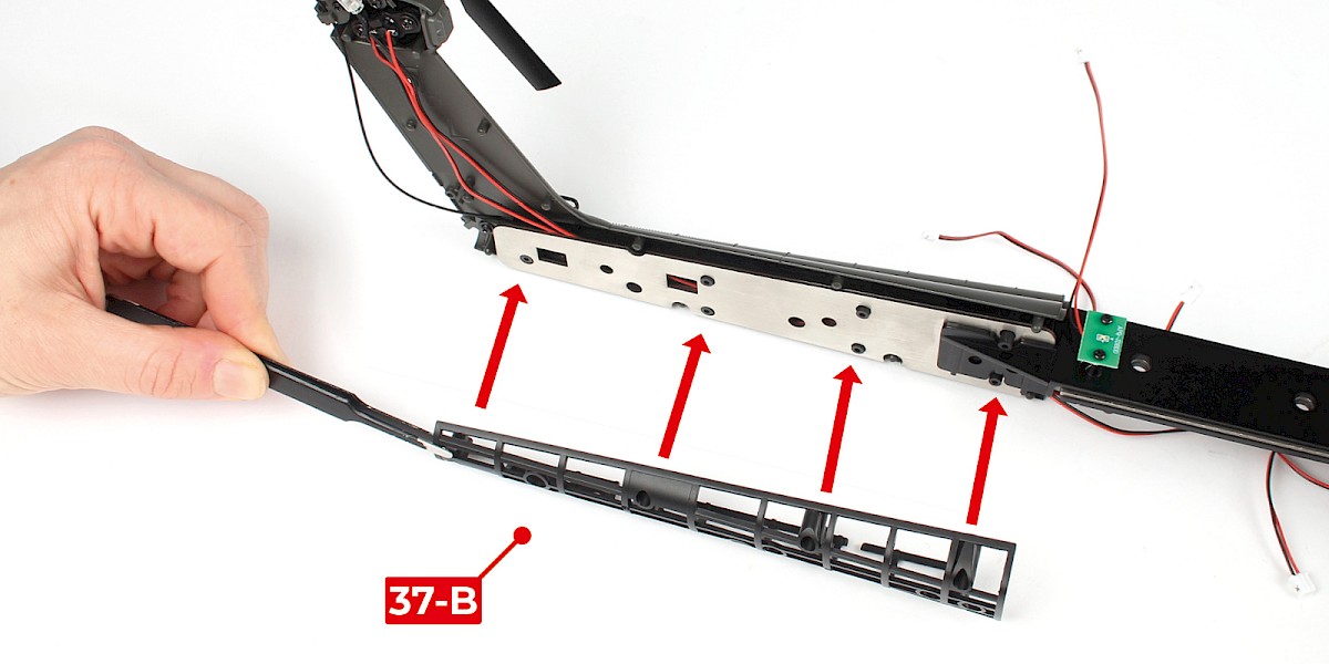
Step 3
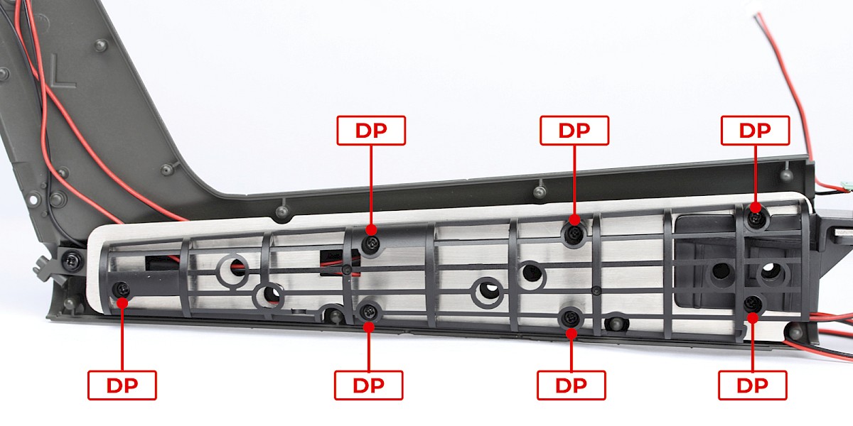
Secure with 7x DP (supplied with stage 37).
Step 4
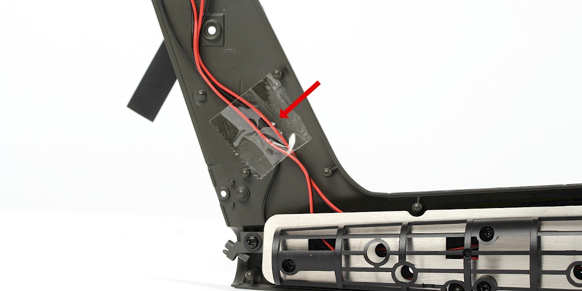
Use a piece of sticky tape to secure the wires and cables as shown.
Step 5
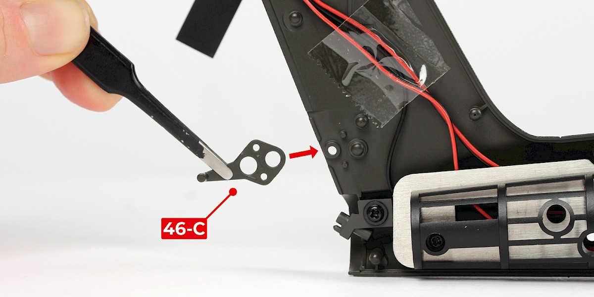
Fit 46-C to the assembly.

Step 6
Make sure none of the cables are crossing over the screw holes (circled) before the next step.
You can gently move the ends of the cables to guide them away from the holes if needed (arrow).
Step 7
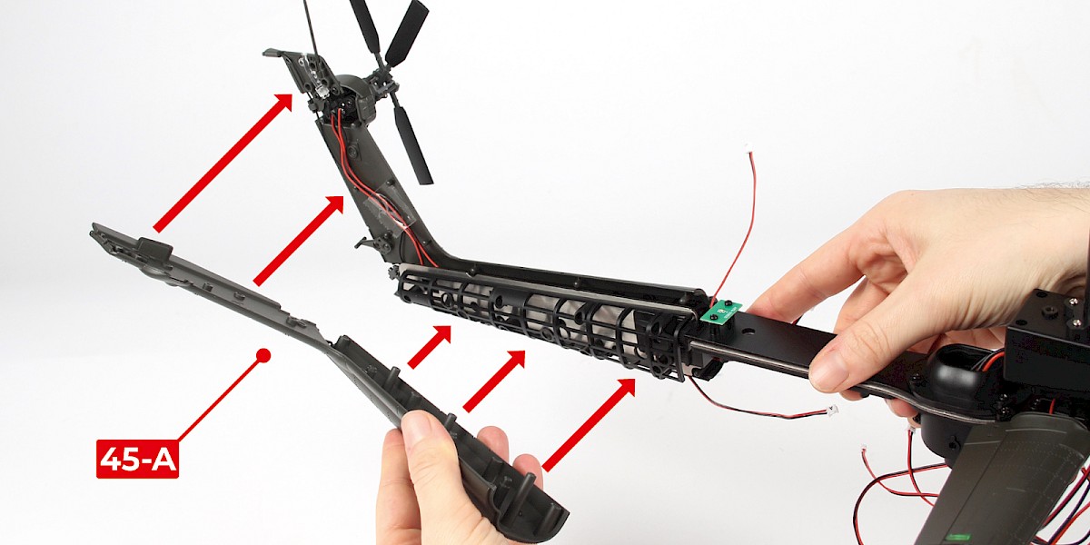
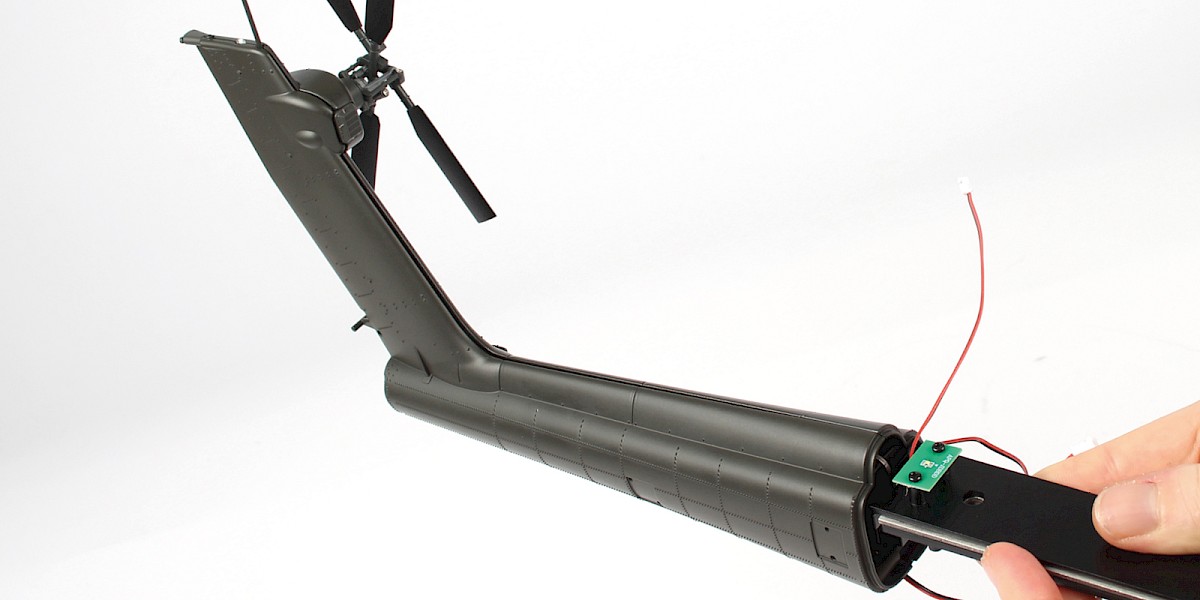
Fit 45-A (stage 45) to the assembly.
Step 8
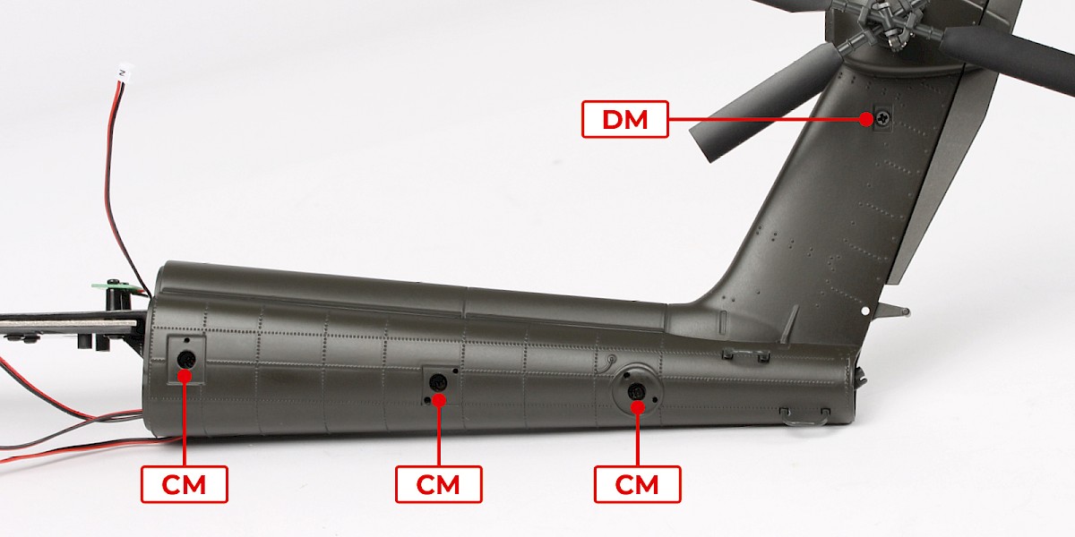
Secure with 3x CM and 1x DM as shown (supplied with stage 45).
Step 9
Whenever you place the assembly on a surface, take care not to damage the step handle (circled).
Step 10
Cut the decals outlined in red from 40-F.
Step 11
Take 46-D and a set of decals.
Apply decals A, B, C and D to 46-D.

Step 12
Repeat step 11 to make 10 rockets.
STAGE COMPLETE
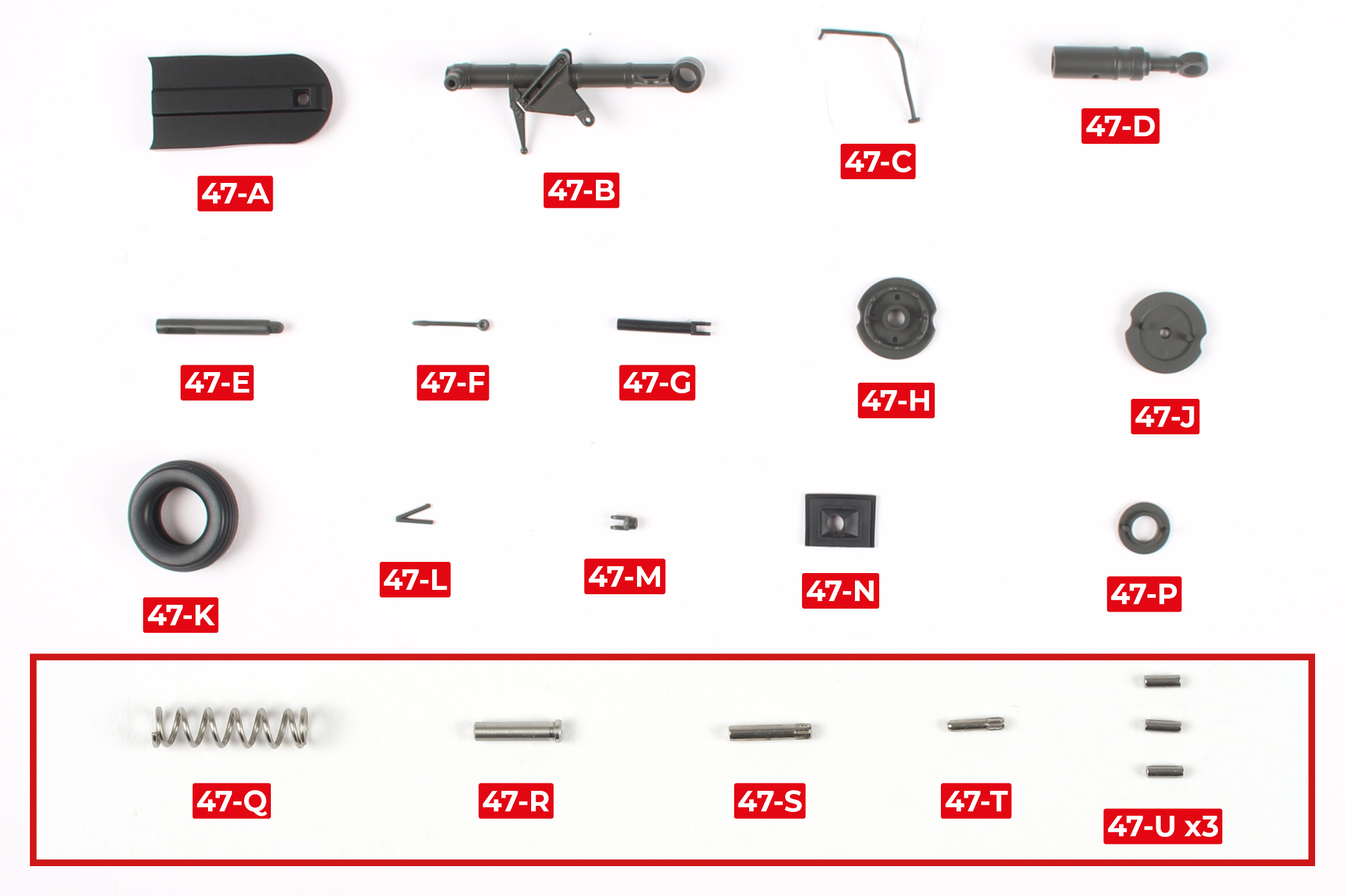
PARTS LIST
| 47-A | 47-H | 47-Q |
| 47-B | 47-J | 47-R |
| 47-C | 47-K | 47-S |
| 47-D | 47-L | 47-T |
| 47-E | 47-M | 47-U x3 |
| 47-F | 47-N | |
| 47-G | 47-P |
* The parts in bold have been magnified in the image below. Some of these parts are very small so be careful not to lose them.
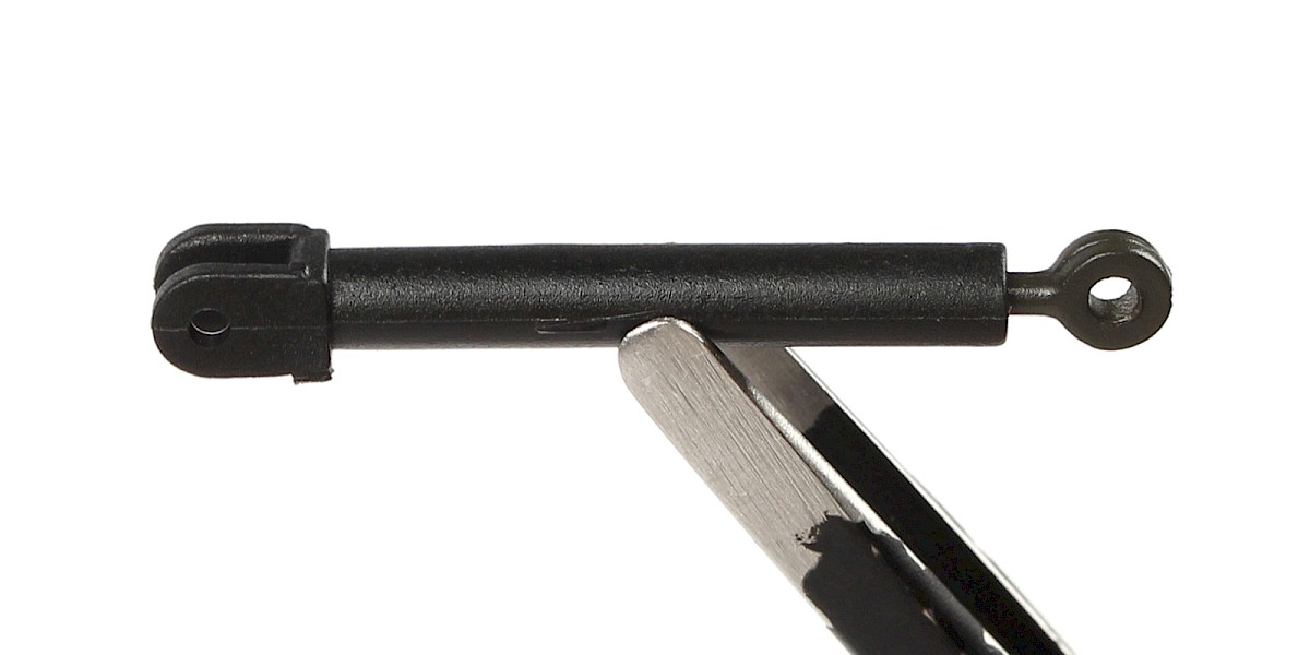
Step 1
Insert 47-F into 47-G.

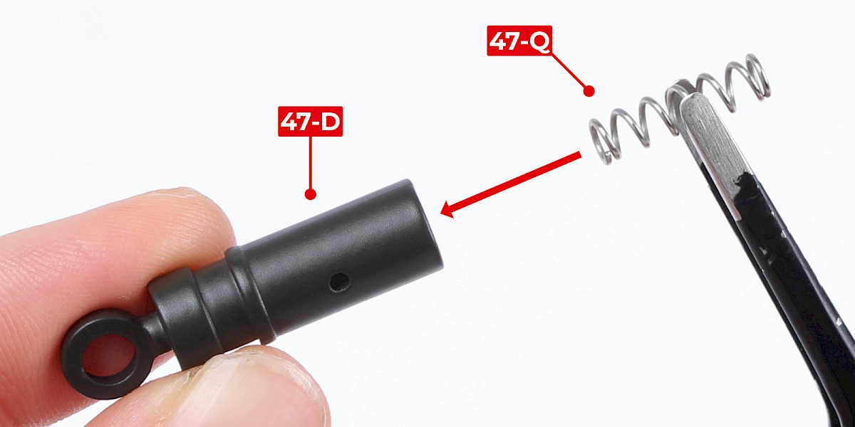
Step 2
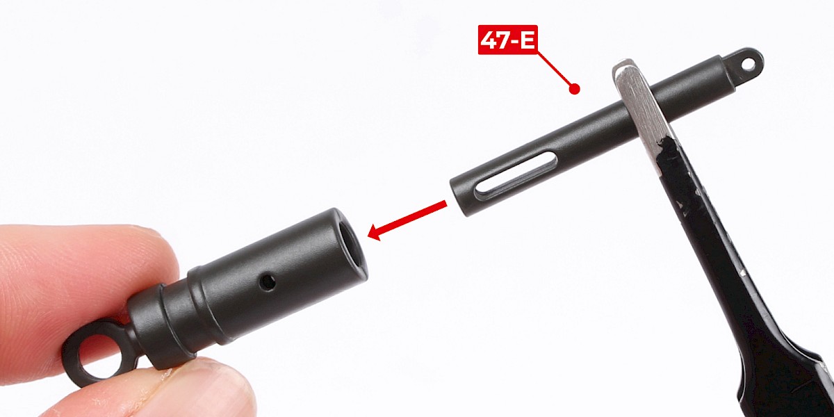
Fit 47-Q into 47-D.
Insert 47-E into 47-D.
Step 3
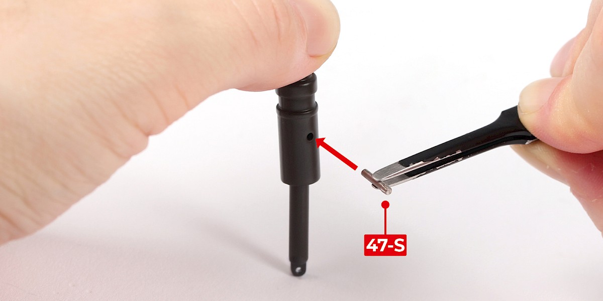
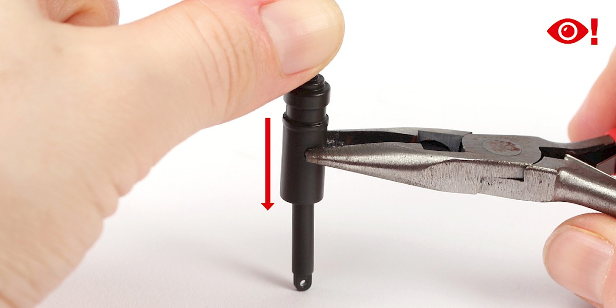
Align 47-S with the assembly.
Compress the spring inside the assembly, then insert 47-S and use pliers to press into place. Take extra care with this step.
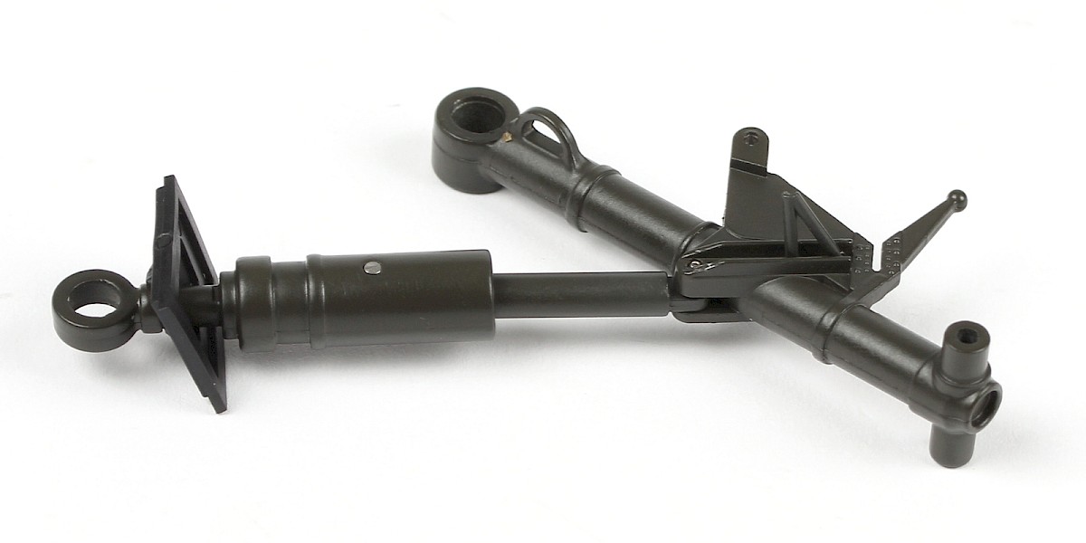
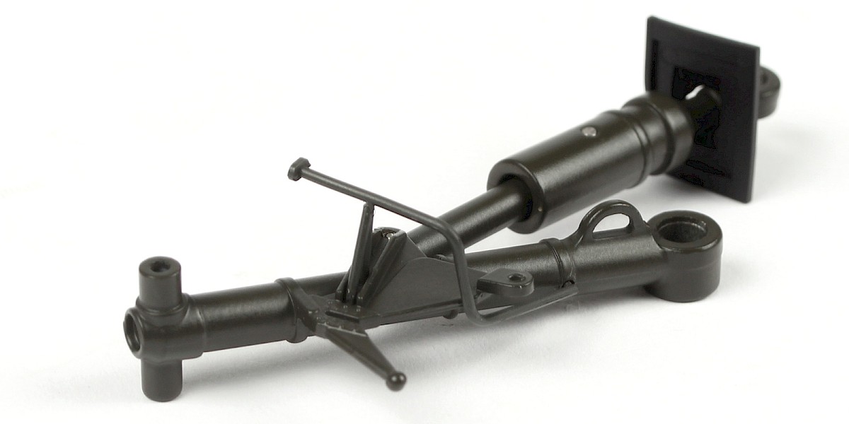
Step 4
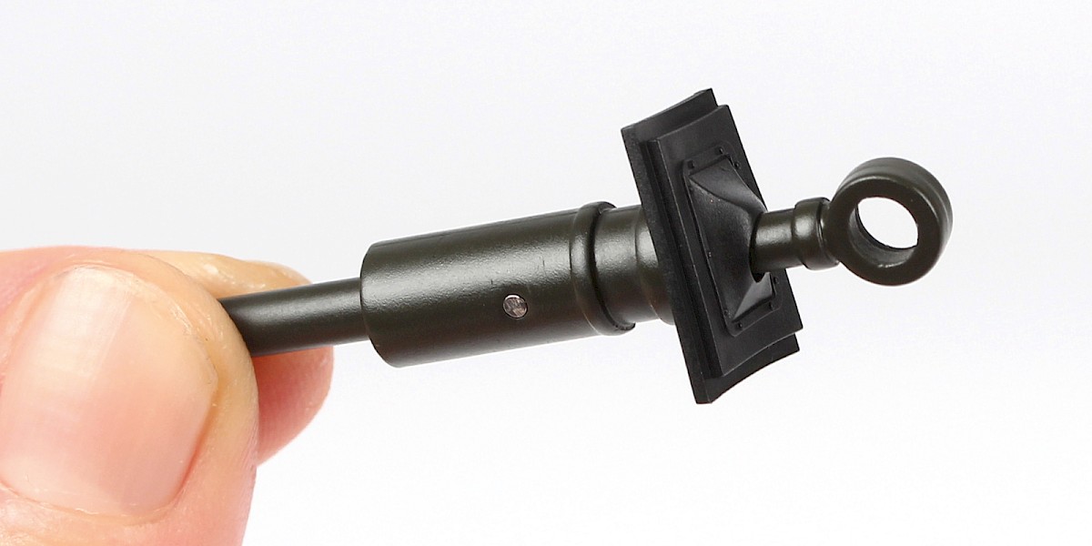
The assembly should look like this once the parts are secured.

Step 5
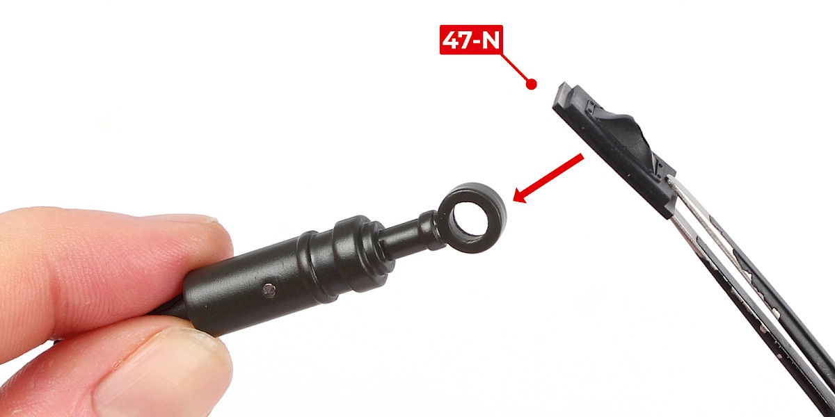
Fit 47-N onto the assembly.
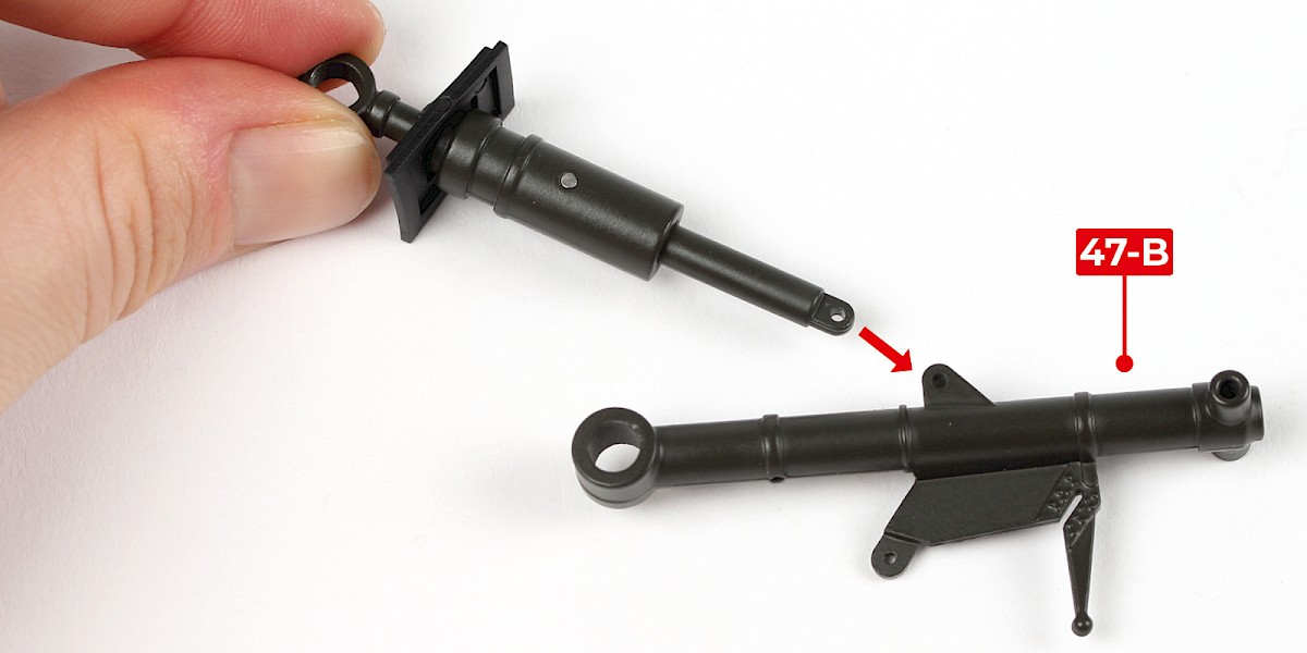
Step 6
Fit the assembly to 47-B.
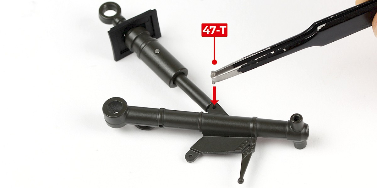
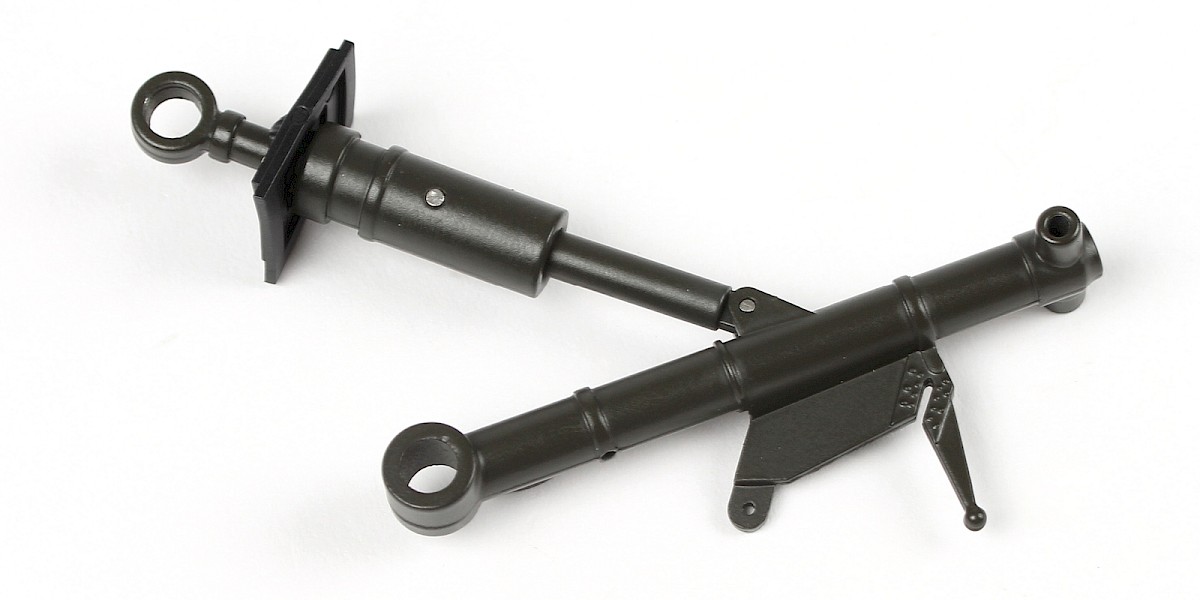
Step 7
Fix in place with 47-T, fitting the smooth end first.
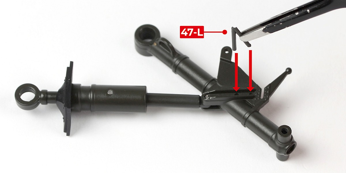
Step 8
Glue 47-L onto the assembly.
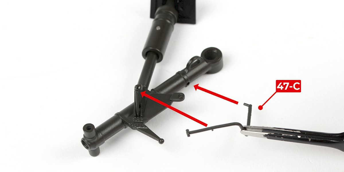
Step 9
Glue 47-C to the assembly.
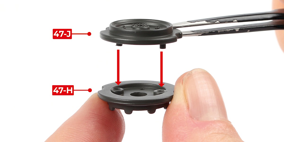
Step 10
Fit 47-J to 47-H.

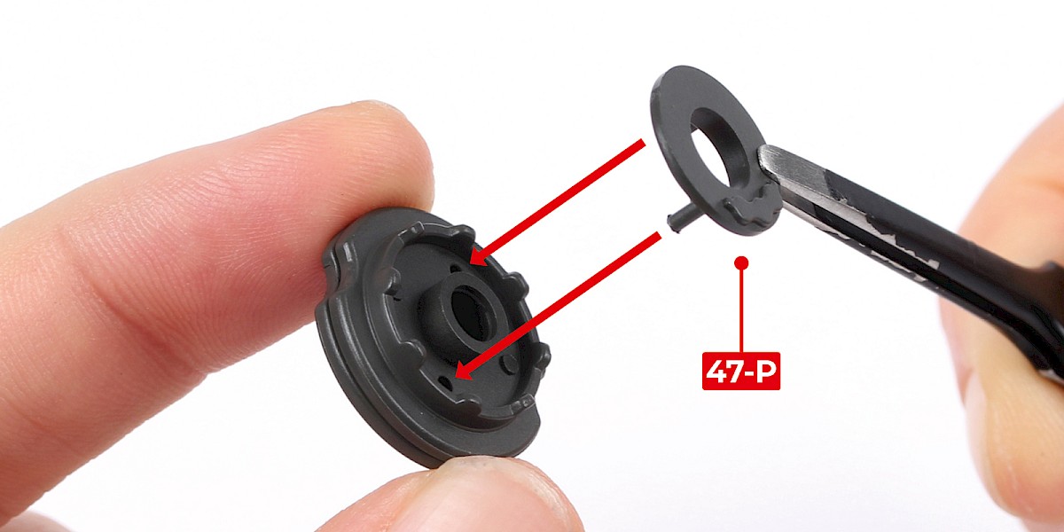
Step 11
Fit 47-P into place.

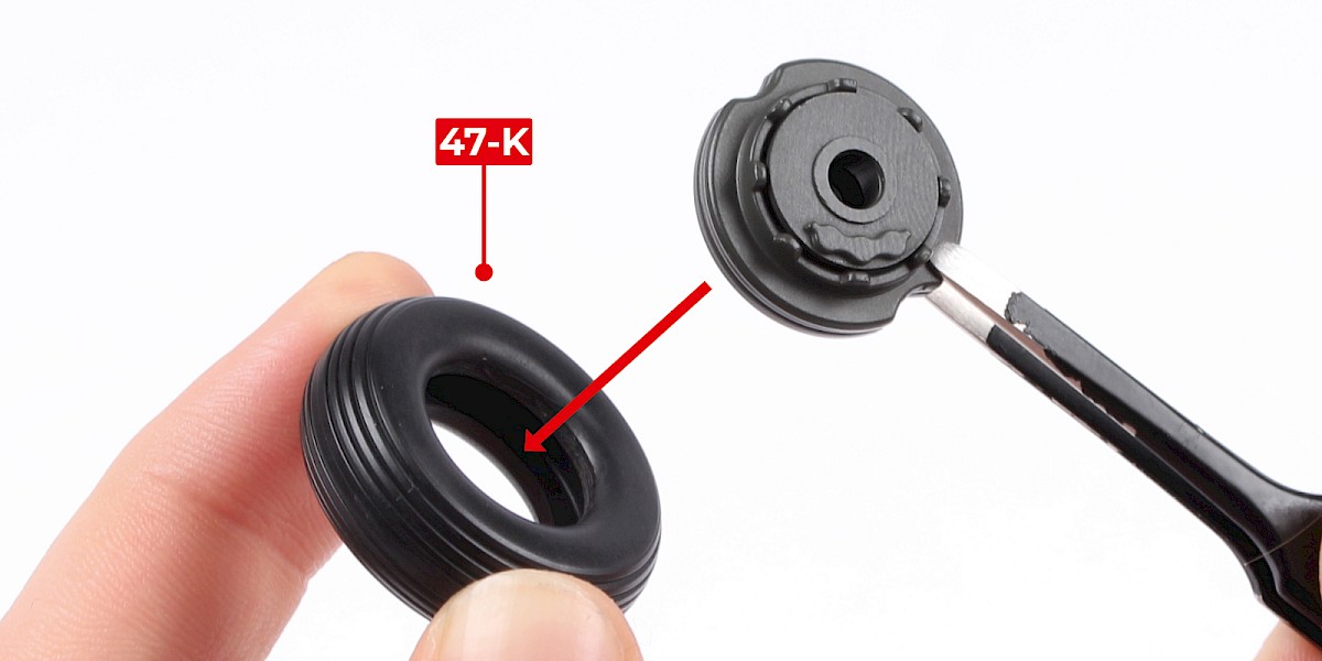
Step 12
Place 47-K into hot water for 1–2 minutes to soften it.
Carefully remove 47-K from the water. Fit the wheel hub into 47-K.

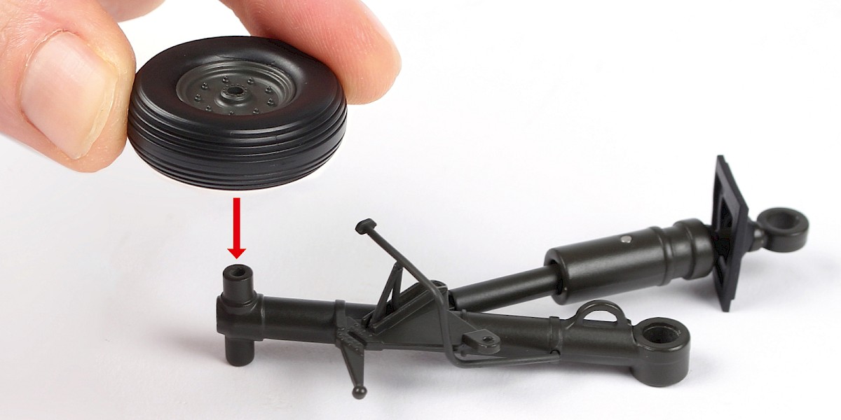
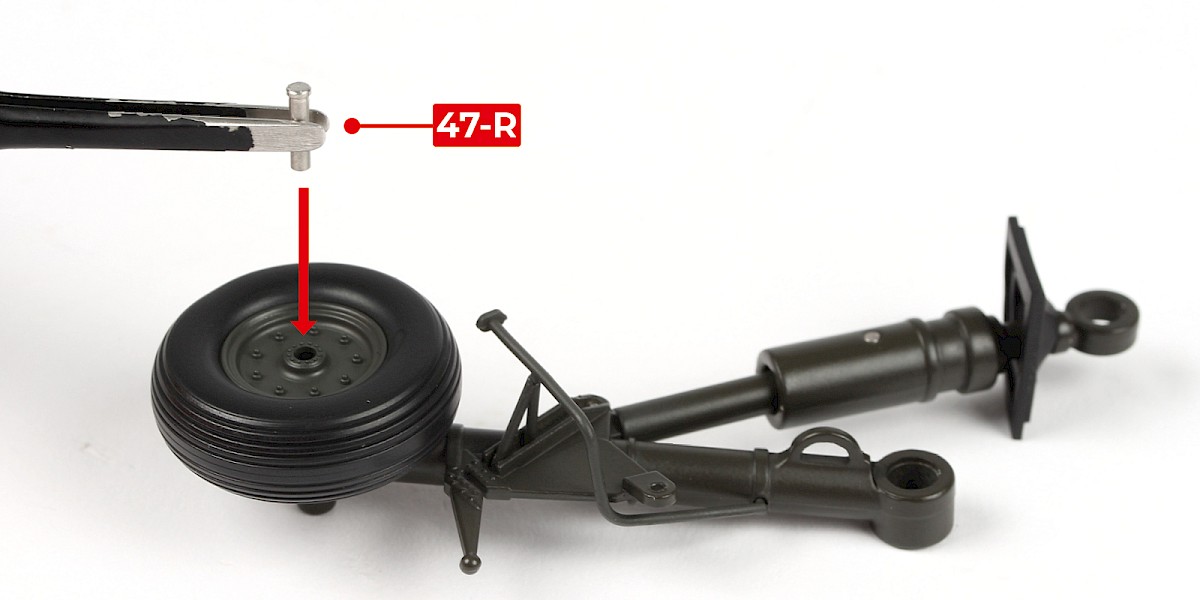
Step 13
Fit the wheel to the assembly.
Step 14
Secure with 47-R, fitting the smooth end first.
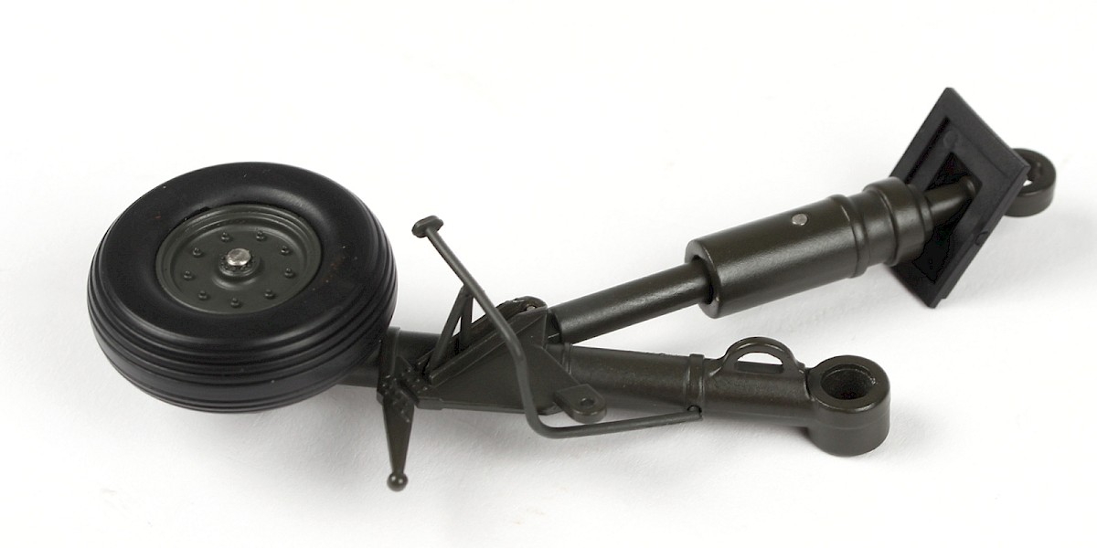
STAGE COMPLETE