
Pack 1
BUILD INSTRUCTIONS
Instructions for building your U.S.S. Constitution model ship
Your model of the U.S.S. Constitution is divided into 12 packs.
You will need to follow the step-by-step assembly photos, the plans and the explanatory texts below.
Please save the leftover materials from each pack for use when instructed to do so at a later stage of the assembly instructions.
The IP sheets displayed below are drawings of laser-cut parts and photo-etched brass parts and will serve as a guide for identification of some parts.
Use the PARTS REFERENCE table to help locate the parts.
The PL-00 templates (printed at 1/1 scale) included in each pack will serve as a guide for building the frames.
Please check the list below to ensure you have all the tools required for building your wooden ship.
When removing a part, cut the ribs that join the part to the wooden plate with a cutter.
Remove the parts carefully so as not to break them.
Keep and store the parts in their frames. Only remove the parts you are working on in each step.
Extra support can be found on our forum or from the Expert Directory page of our website.
PARTS LIST
| Material | Quantity | |
| Boards 2001-1 – 2001–9 | Wood | 9 |
| Wooden Strips | ||
| 5 x 5 x 400 mm | Oak | 14 |
| 3 x 3 x 400 mm | Lime wood | 7 |
| 2 x 3 x 600 mm | Lime wood | 5 |
| Rod Diameter 10 mm x 450 mm | Mahogany | 1 |
| Tools | ||
| Brushes | 3 | |
| Satin Varnish | 2 | |
| Assembly template PL-01 | 1 | |
| Assembly template PL-02 | 1 |
Tools you will need: cutting mat, pencil, cutting knife, fine-grit sandpaper or sponge sandpaper, file, white wood glue, super glue (cyanoacrylate glue), masking tape, set square, hacksaw, sanding block, 30 cm steel ruler, clamps
PACK 1 IDENTIFICATION SHEETS
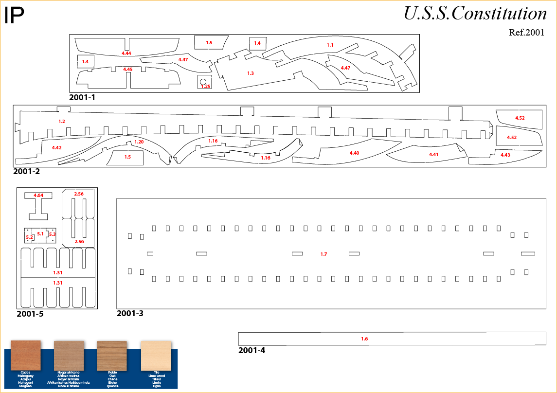
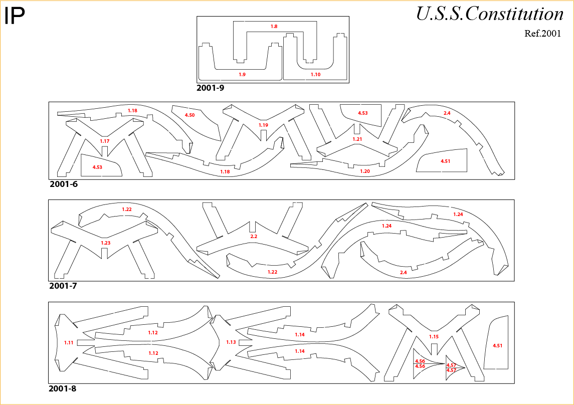
PARTS REFERENCE
PART NO. | IP-SHEET LOCATION | PART NO. | IP-SHEET LOCATION | PART NO. | IP-SHEET LOCATION |
| 1-1 | 2001-1 | 1-7 | 2001-3 | 1-13 | 2001-8 |
| 1-2 | 2001-1 | 1-8 | 2001-9 | 1-14 | 2001-8 |
| 1-3 | 2001-1 | 1-9 | 2001-9 | 1-15 | 2001-8 |
| 1-4 | 2001-1 | 1-10 | 2001-9 | 1-16 | 2001-2 |
| 1-5 | 2001-1 | 1-11 | 2001-8 | 1-17 | 2001-6 |
| 1-6 | 2002-4 | 1-12 | 2001-8 | 1-18 | 2001-6 |
Step 1
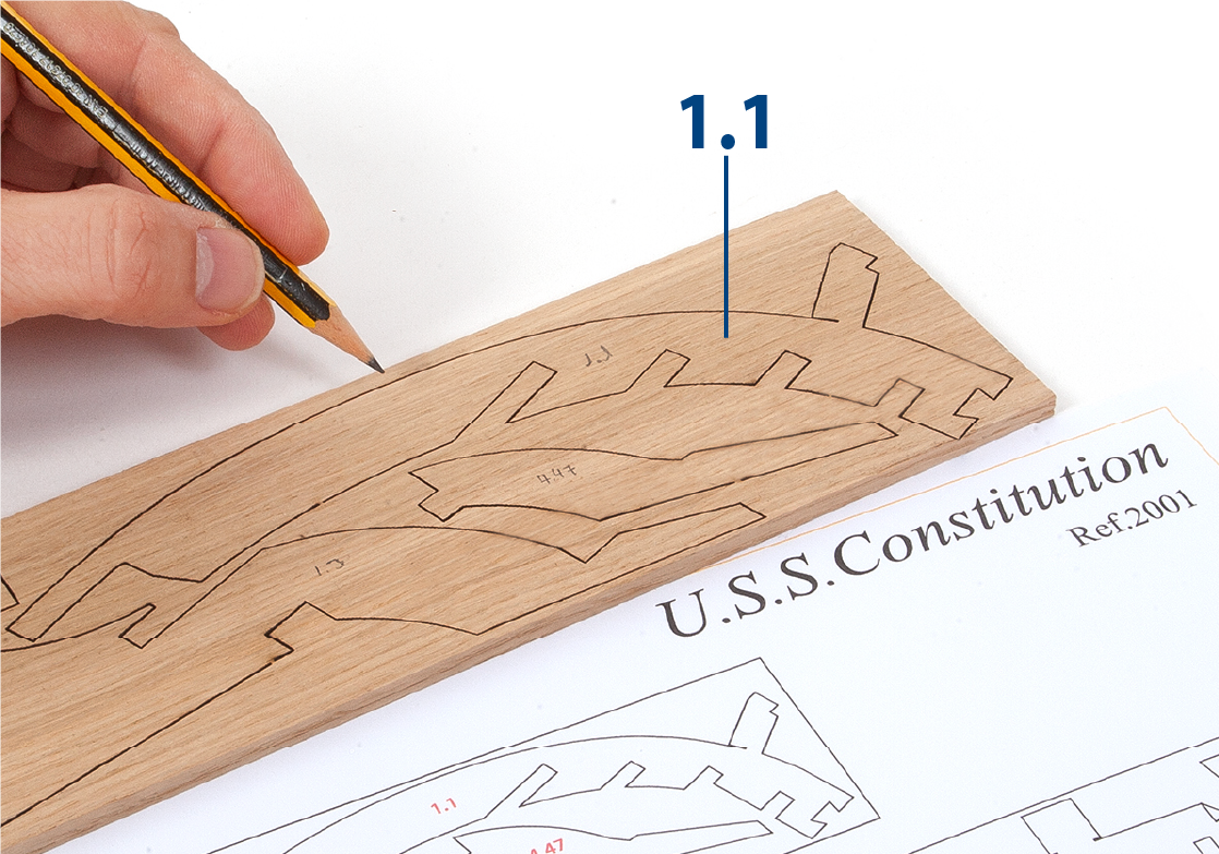
Use a pencil to transfer the numbers from the IP sheets (PACK 1 IDENTIFICATION SHEETS above) to the wooden boards.
Step 2
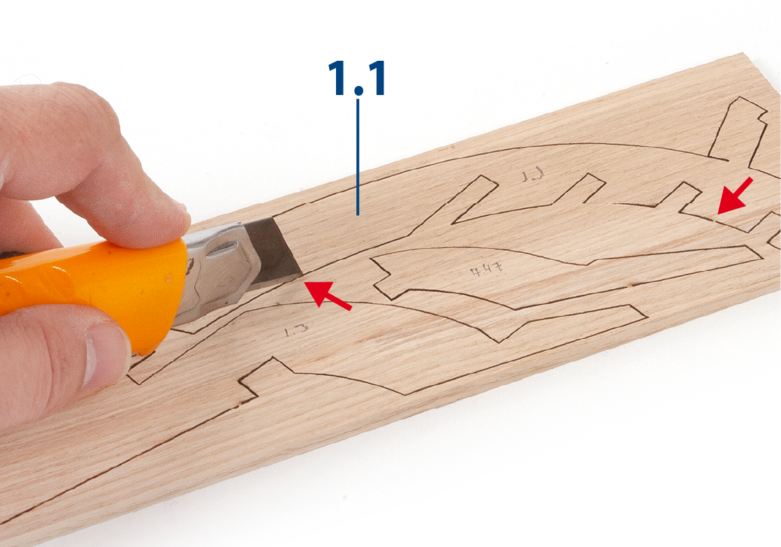
Cut the ribs that join the pieces to the boards with a cutter, so that they can be removed without damaging them.
Only remove the parts you are working on in each step.
Step 3
Remove the parts from the boards carefully so as not to break them.
Step 4
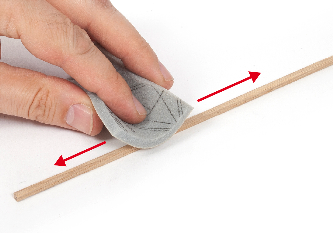
Place the parts on a flat surface and sand them with fine-grit sandpaper or sponge-sandpaper to remove any possible wood flaking.
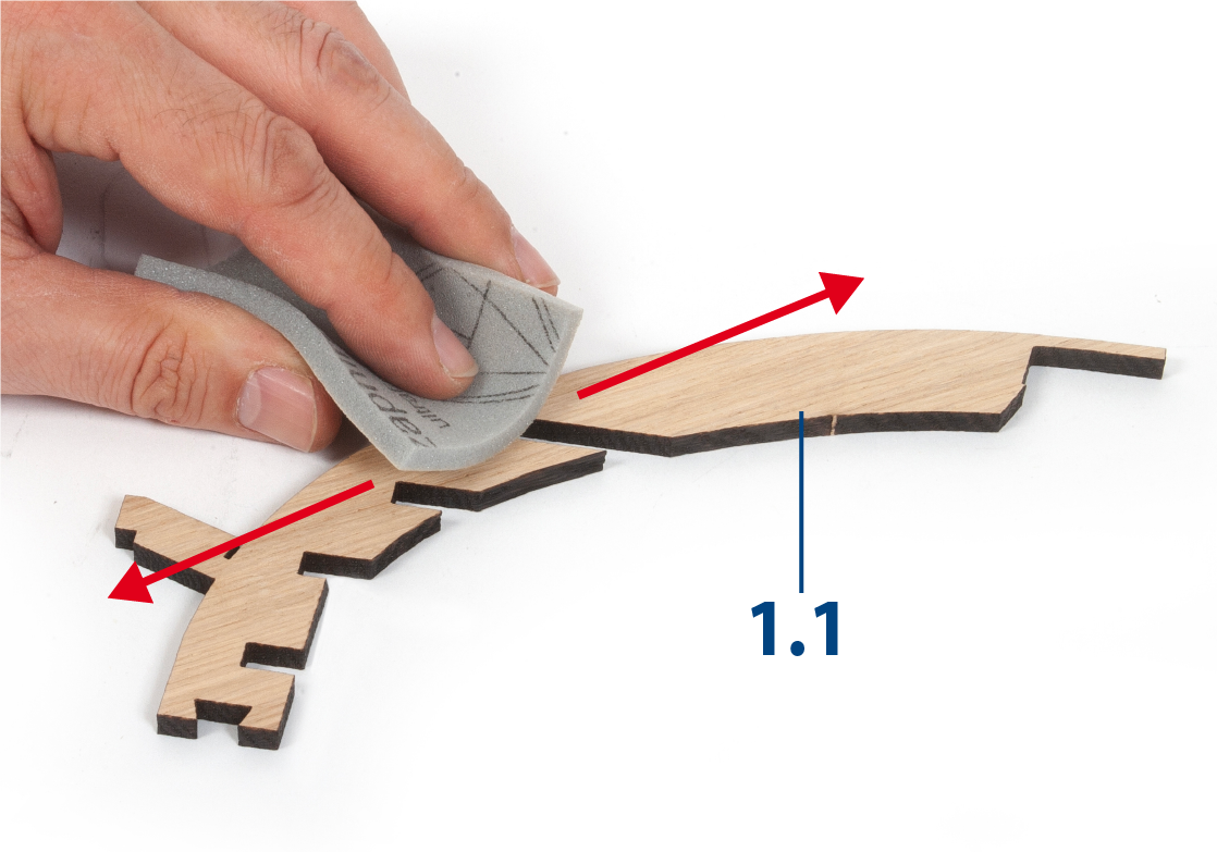
Step 5
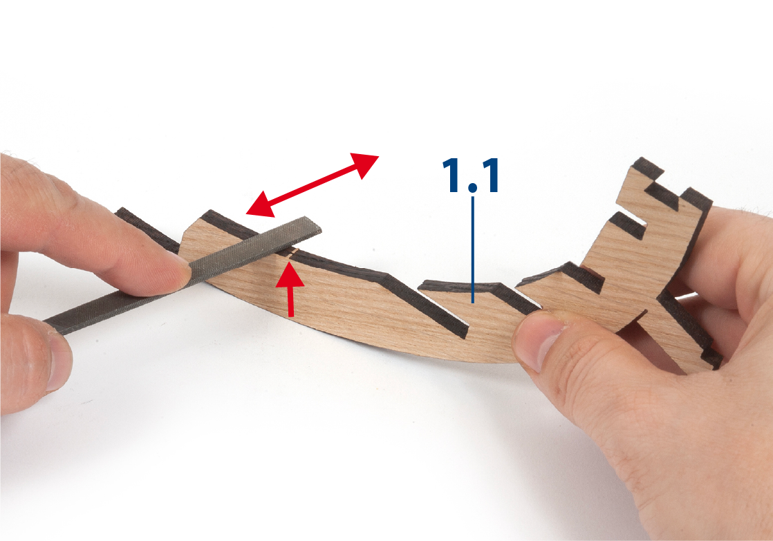
Use a file to remove the remnants of the connecting ribs from the parts.
You can also color in the ribs using a felt tip pen.
Step 6
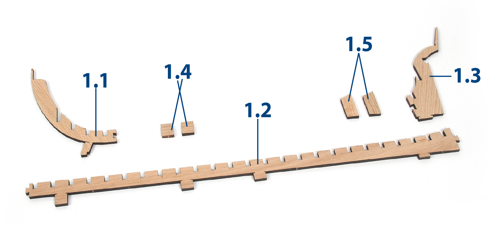
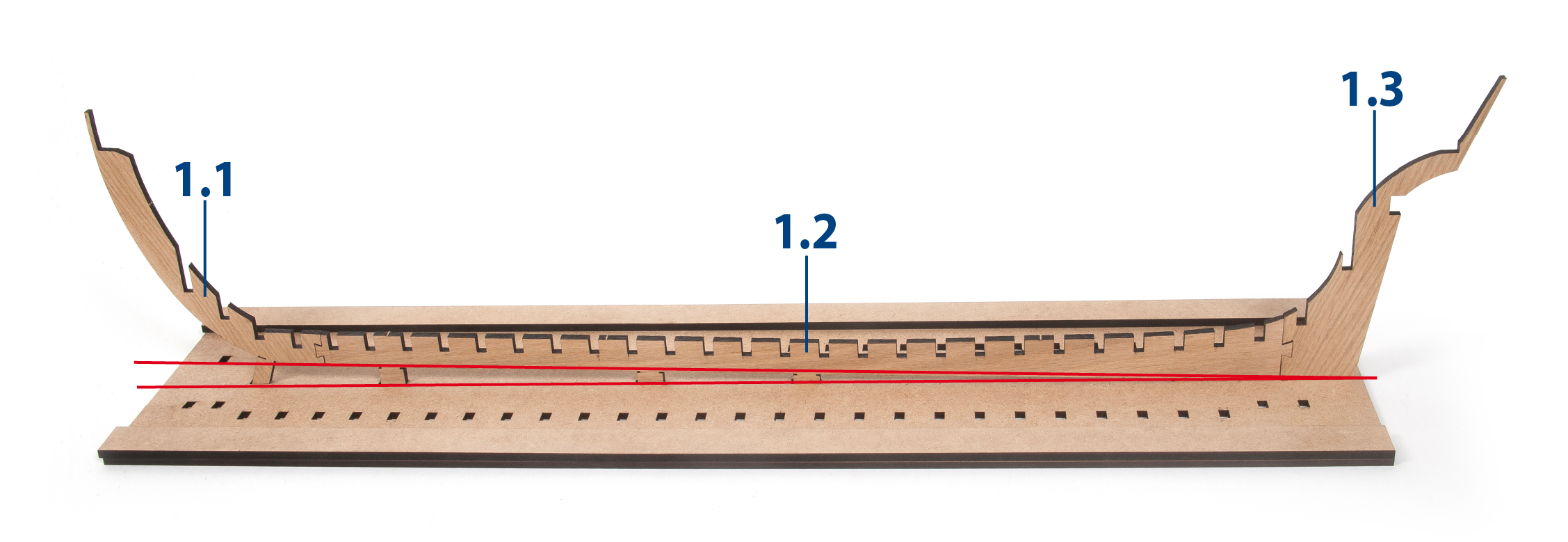
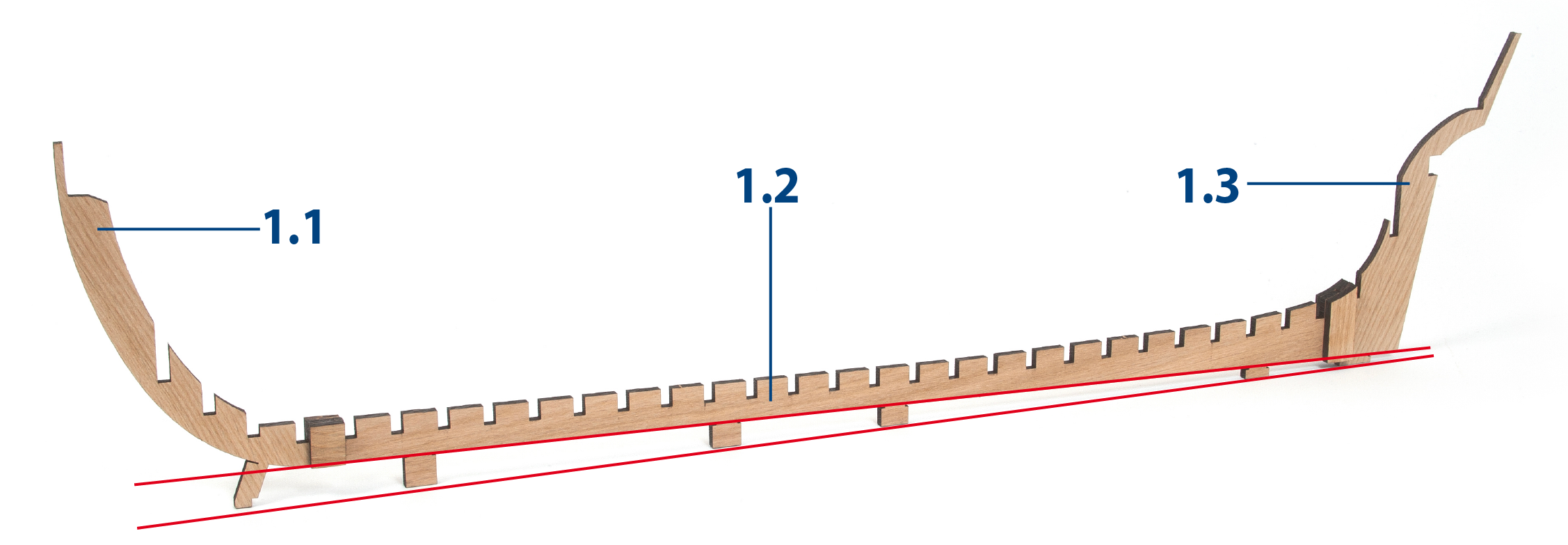
To construct the complete false keel you will need parts 1.1 to 1.5.
Step 7
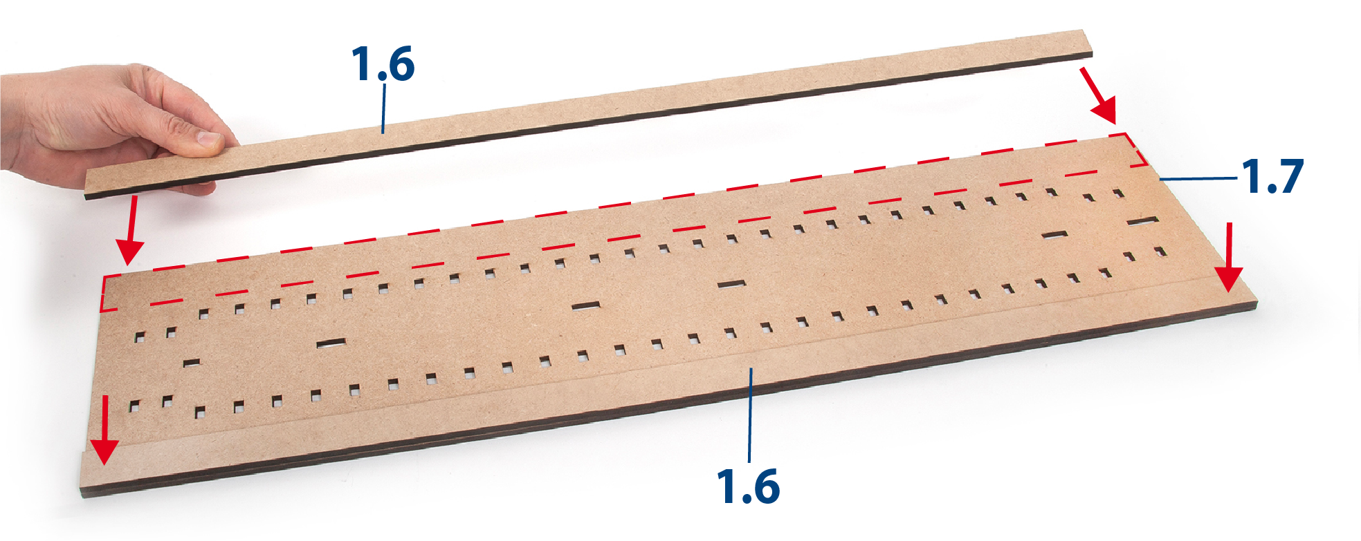
Apply white glue (carpenter's glue) to one side of the two pieces 1.6.

Step 8
Place part 1.7 on a flat and stable surface. Glue parts 1.6 flat along each edge of part 1.7.
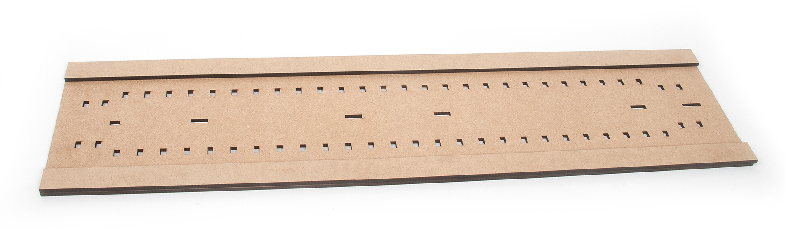
Step 9
Keep the parts immobilised until the glue dries. It is important that these parts are kept in a flat position.
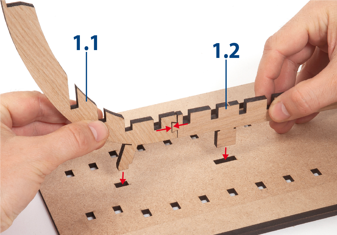
Step 10
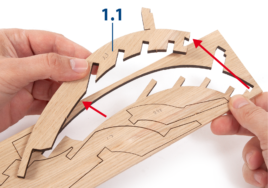
Insert part 1.1 with part 1.2, without gluing them together. Insert the two parts into the grooves of the base as far as they will go.
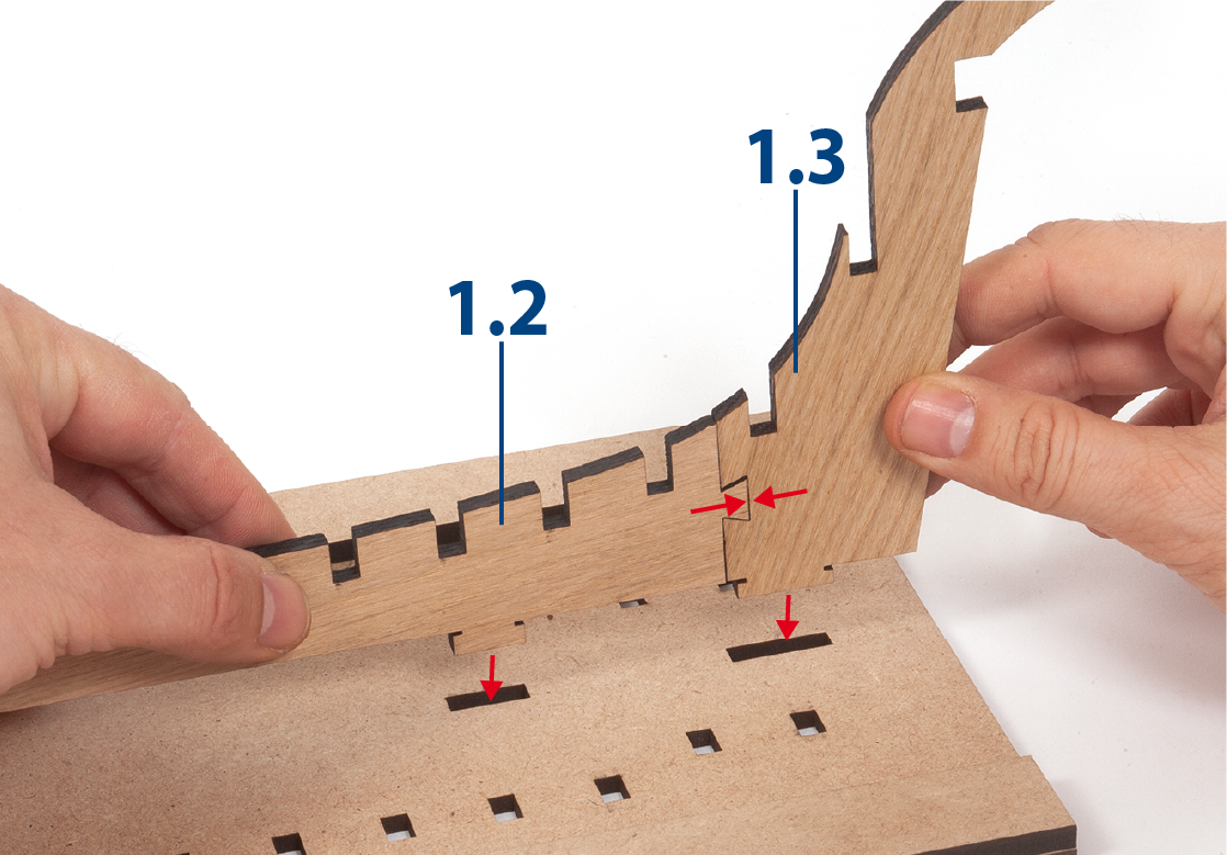
Step 11
Proceed in the same way to insert part 1.2 with part 1.3, without gluing them together, into the grooves of the base.
Step 12
This base will be used to align parts 1.1, 1.2 and 1.3 and the frames when fitting them. Do not glue the parts to the base. Note that parts 1.1 and 1.2 are raised above the plane.
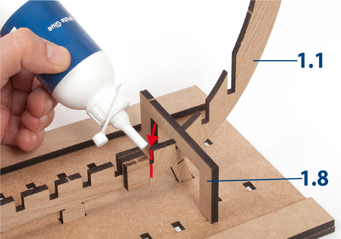
Step 1
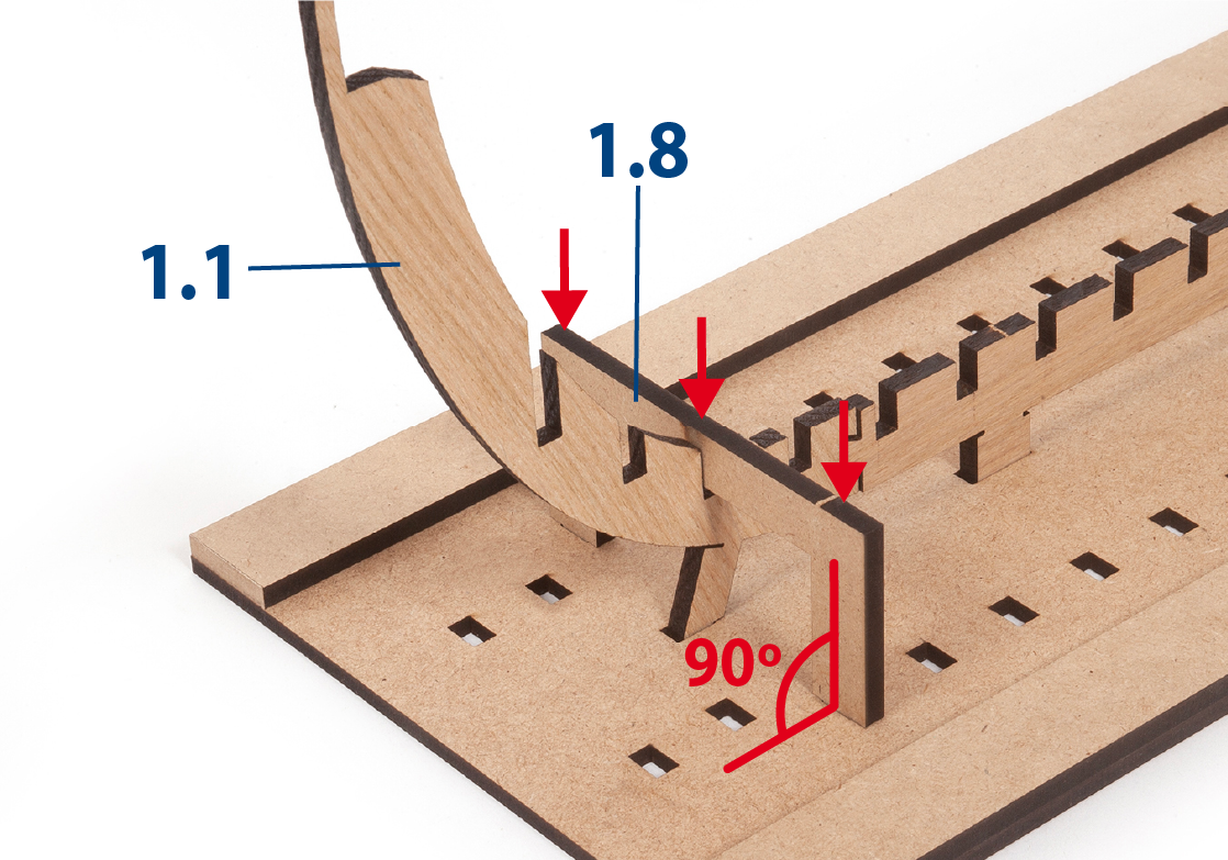
Insert part 1.8 into the groove of part 1.1 and into the base. Do not glue part 1.8.
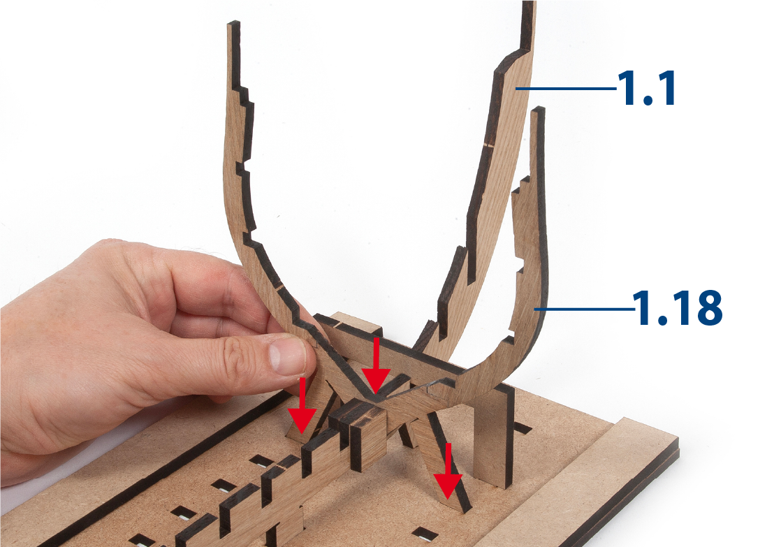
Step 2
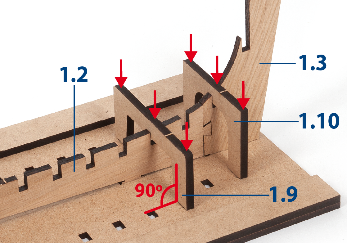
Proceed in the same way to insert parts 1.9 and 1.10 without gluing, so that the parts are immobilised in the base.
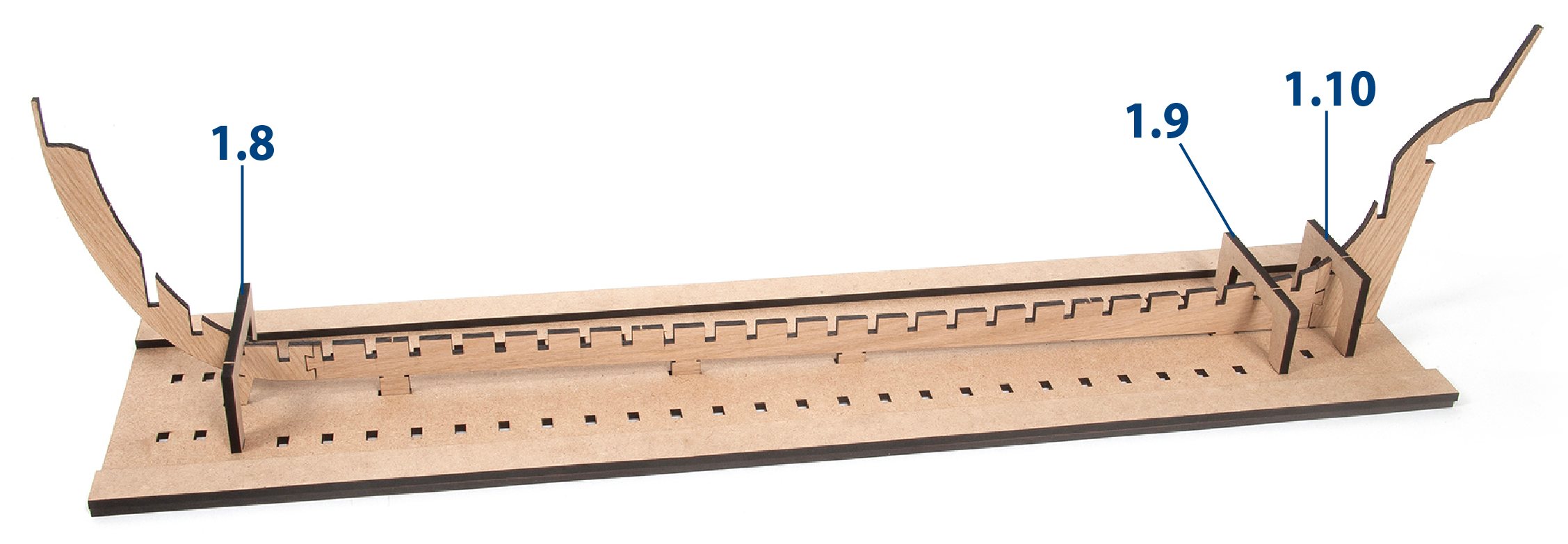
Step 3
In this picture we show you how the pieces that form the false keel of the boat should look on the mounting base.
Step 4
Apply white glue to one side of the parts 1.5.
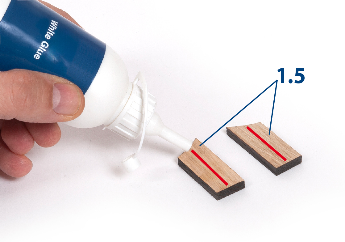
Step 5
Glue one part 1.5 on each side of the joint of parts 1.2 and 1.3. Note that the parts must be joined and aligned. Parts 1.9 and 1.10 must not be glued to the assembly.

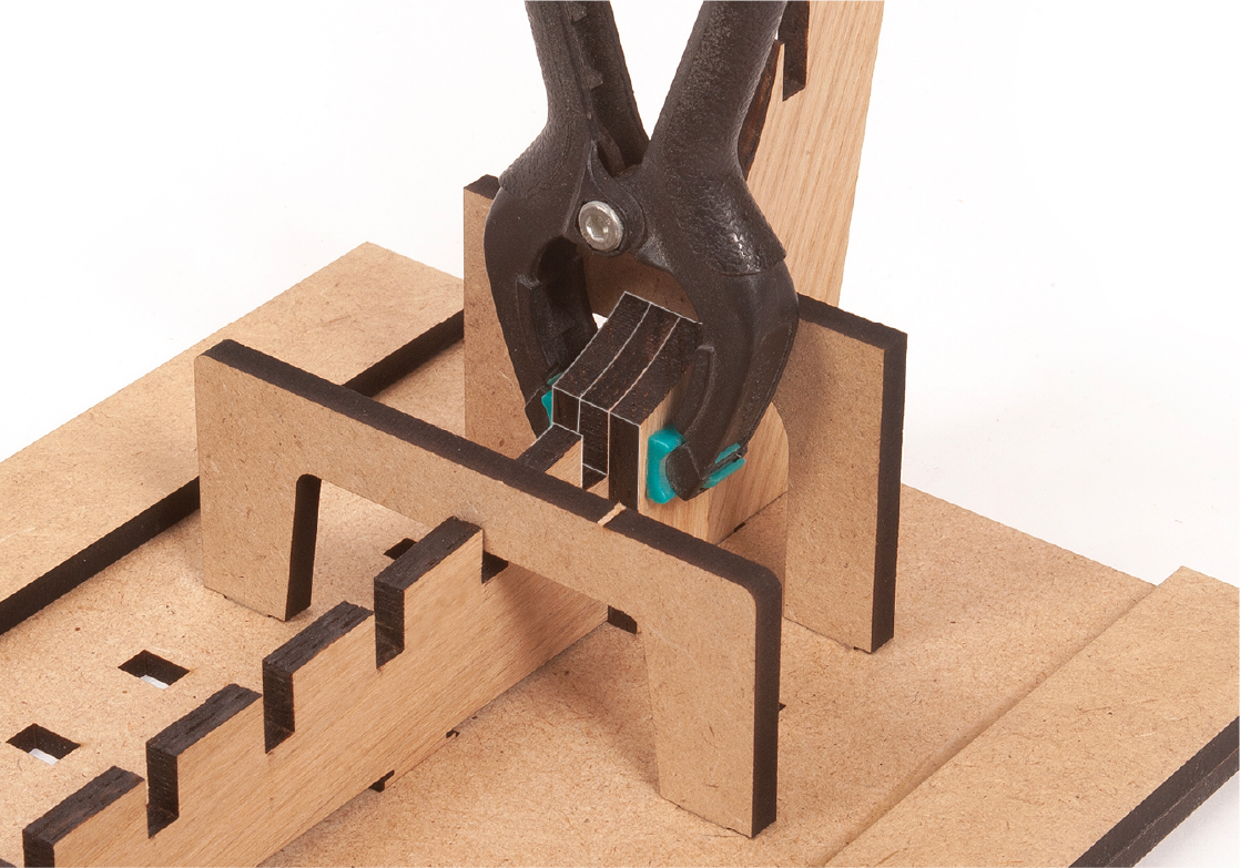
Step 6
Secure the parts together using a clamp or similar. Keep the parts tight and immobilised on the mounting base at all times.
Step 7
Apply white glue to one of the faces of the parts 1.4.
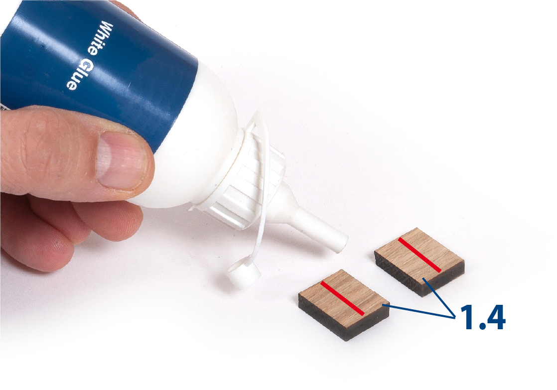
Step 8
Glue one part 1.4 on each side of the joint of parts 1.1 and 1.2. Part 1.8 must not be glued to the assembly.
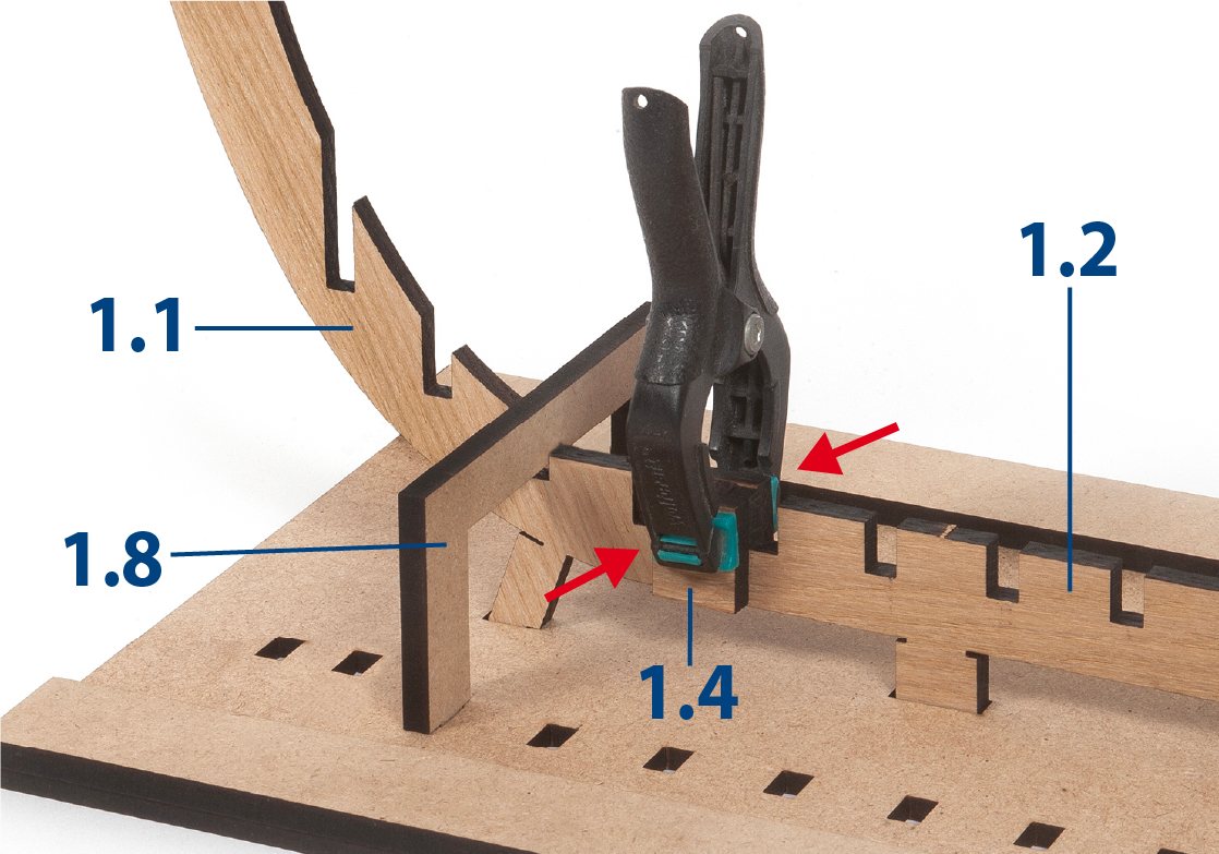
Step 9
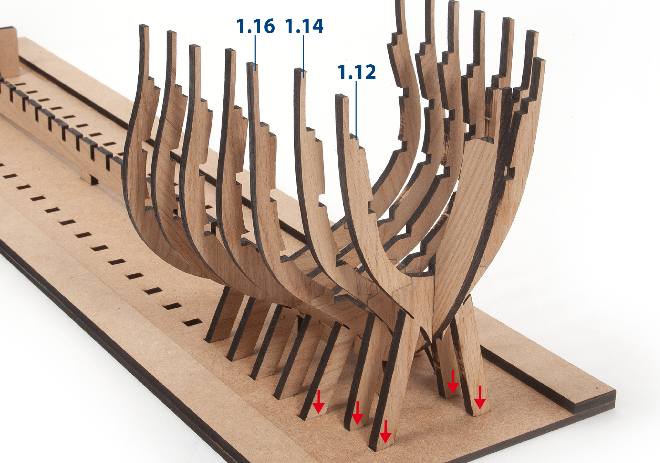
In the picture you can see how the false keel will be higher at the front than at the rear.
Step 10
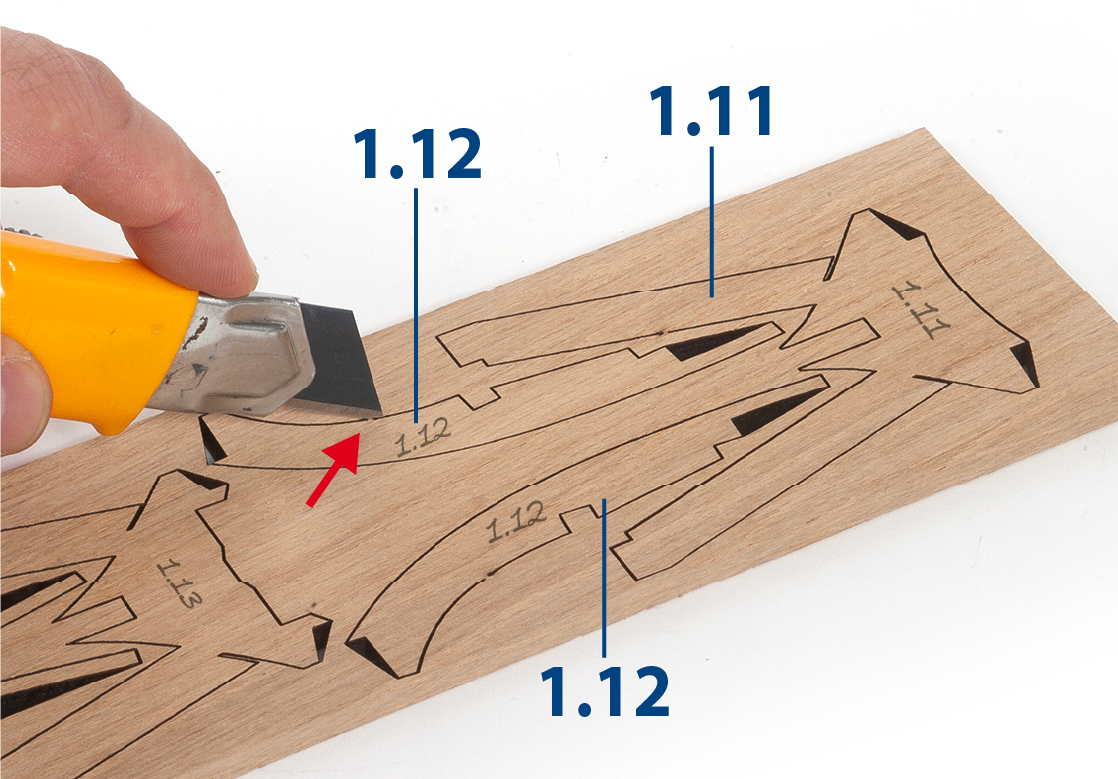
You will now need parts 1.11 and 1.12. Cut the ribs that join the pieces to the boards with a cutter, so that they can be removed without damaging them.
Step 11
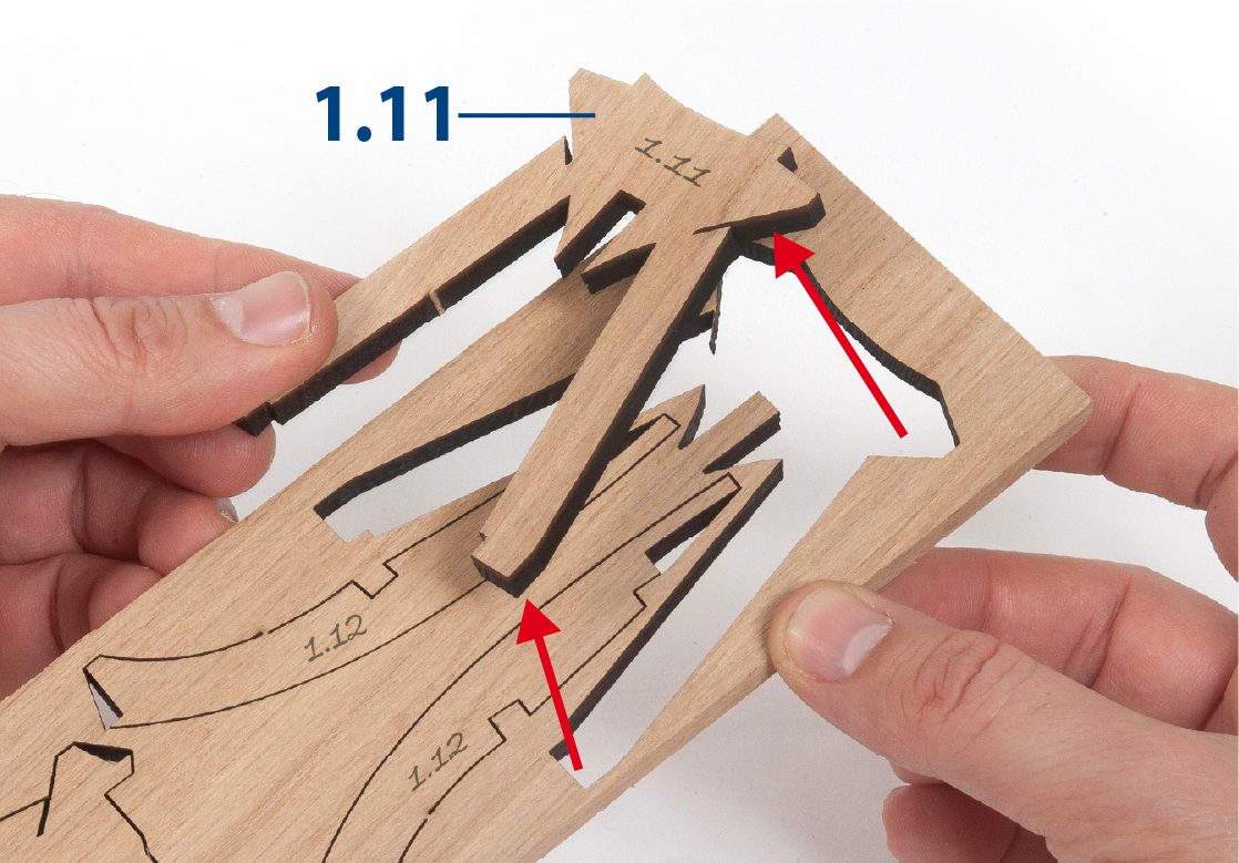
Remove the parts from the boards carefully so as not to break them.
Step 12
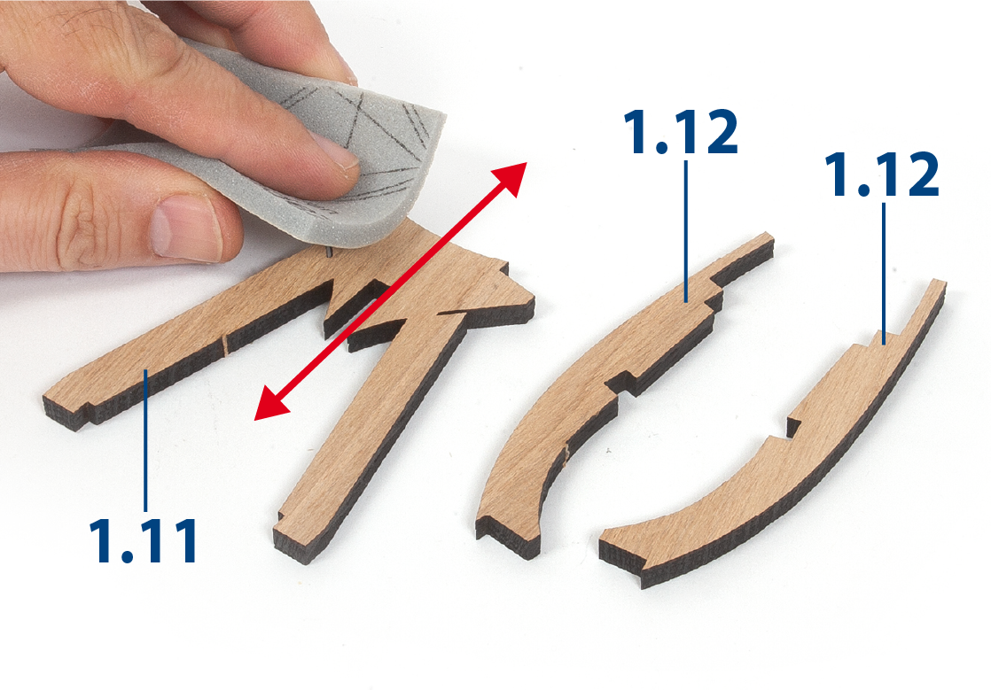
Place the parts on a flat surface and sand them with fine-grit sandpaper or sponge-sandpaper to remove any possible wood flaking.
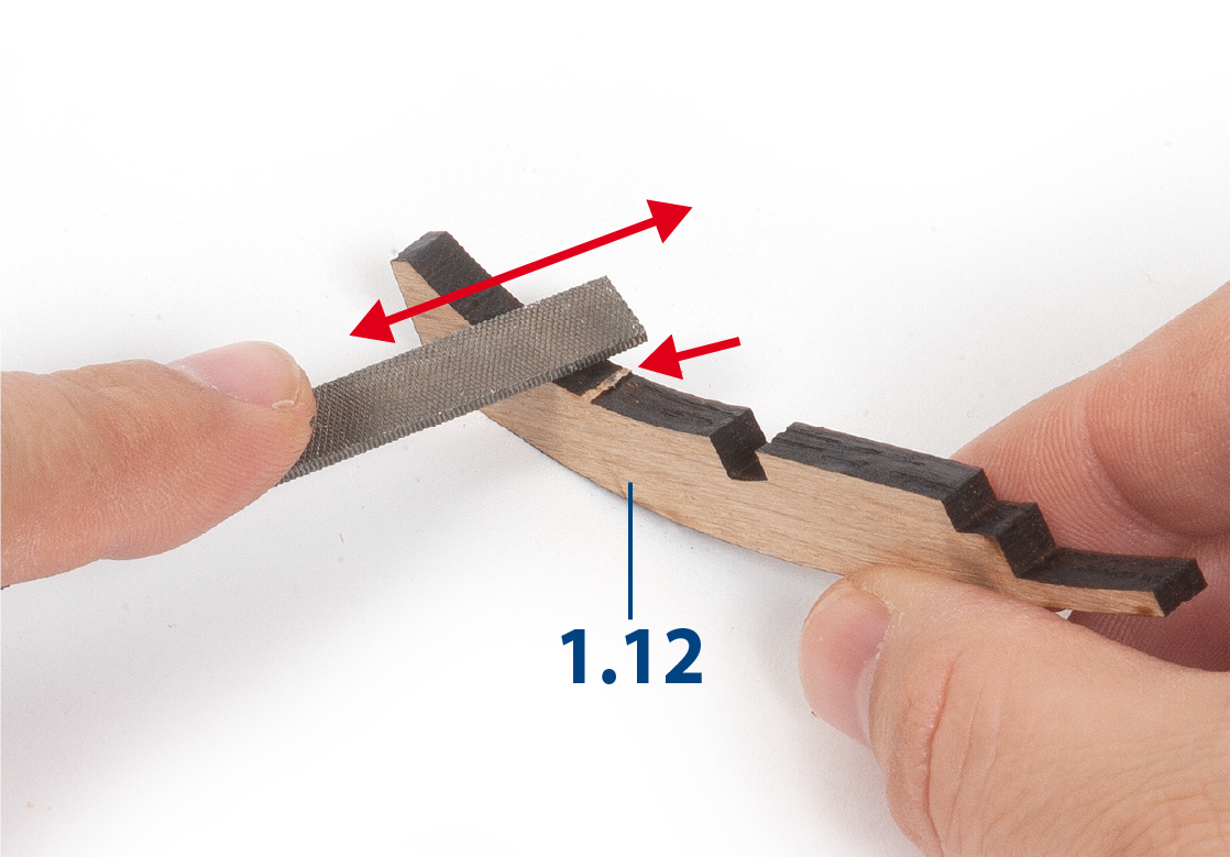
Step 13
Use a file to remove the remnants of the connecting ribs from the parts.
Step 1
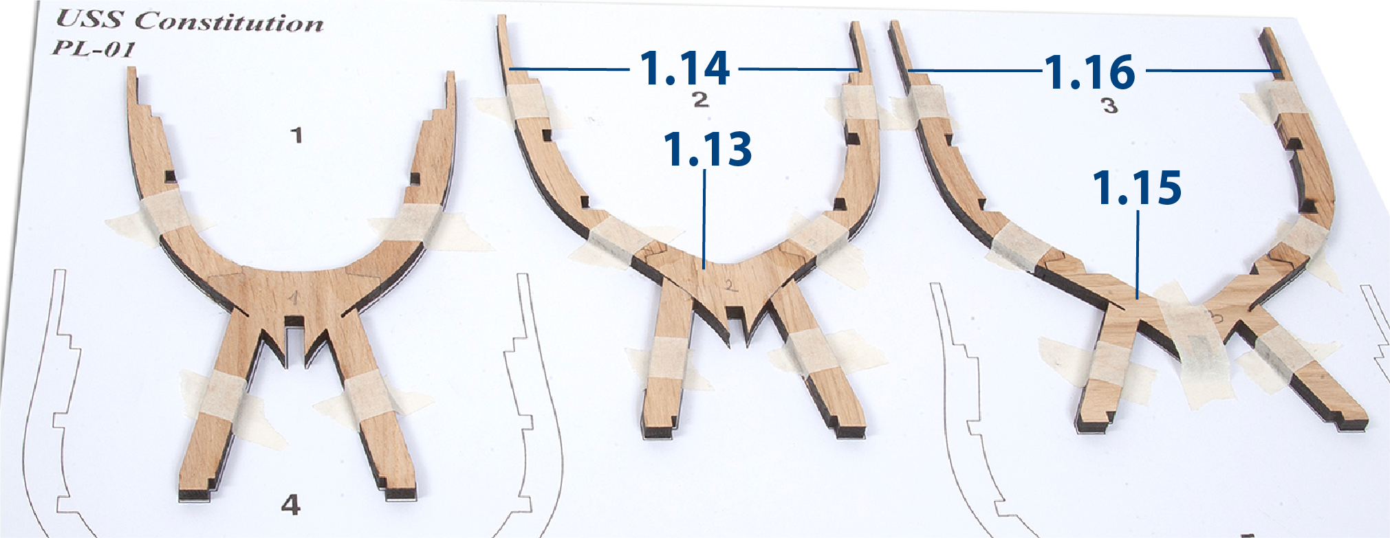
Templates PL-01 and PL-02 will serve as a guide for building the frames. Place parts 1.11 and 1.12 on the figure of frame 1 to check their fit.
![]() Watch our video for extra guidance.
Watch our video for extra guidance.
Expert's advice: correct alignment can also achieved by placing the templates on a pin board before covering with cling film. This will prevent the glue from bonding to the plans and the parts can be held in place using pins.
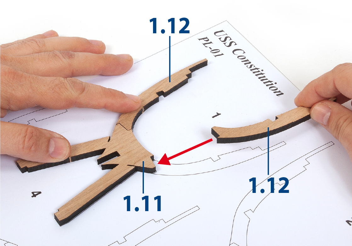
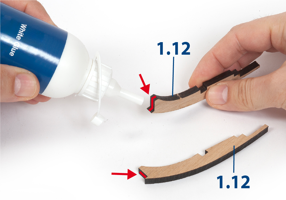
Step 2
Then, apply white glue to the ends of the pieces 1.12. Glue the pieces together to form frame 1.
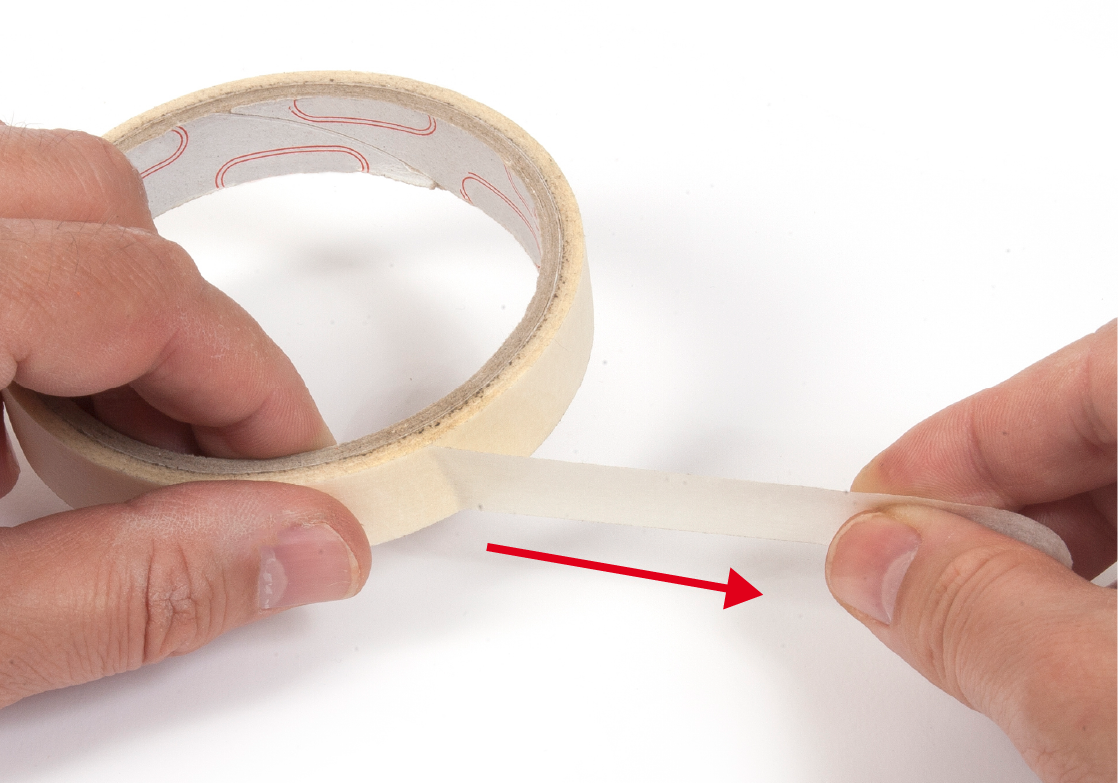
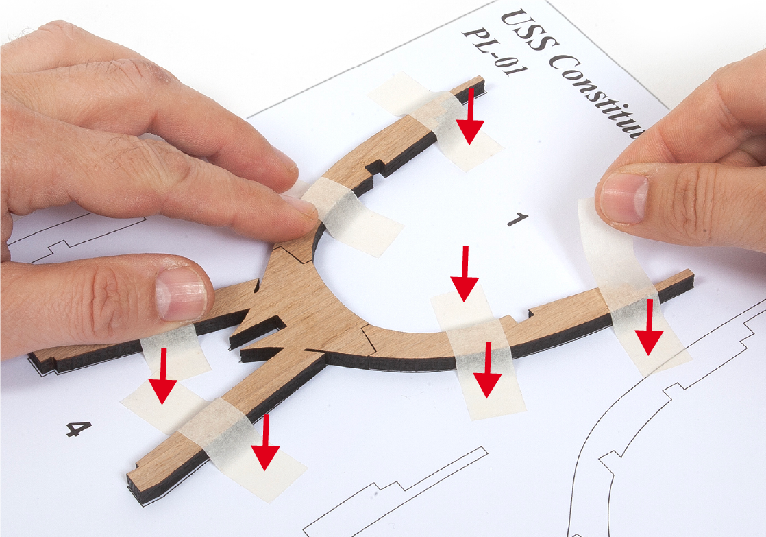
Step 3
Use pieces of masking tape (painter's tape) to immobilise the parts on the template until the glue dries.
Step 4
The parts should be glued together, but not glued to the template. Cover the template with cling film to stop any glue bonding to the template.
Step 5
Follow the same procedures to check and construct frames 2 to 7. Note: Frames 8 and 9 will be completed in Pack 2.
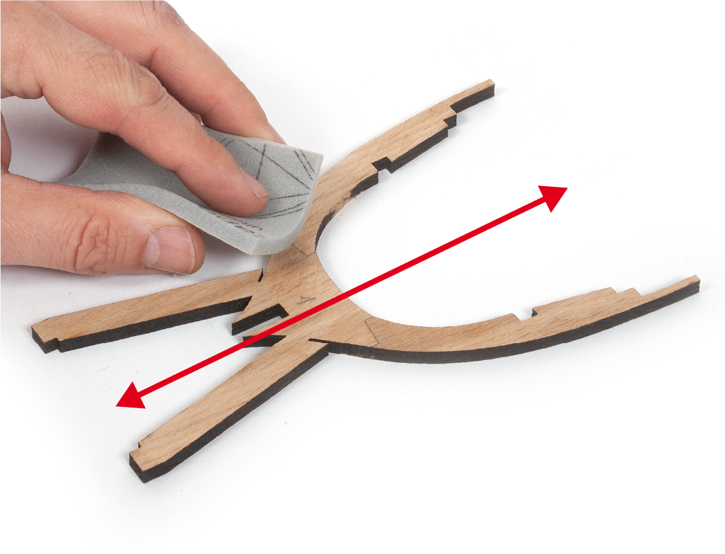
Step 6
Go over the frames with a fine-grit sponge sander to remove any glue or paper that may have stuck to them.
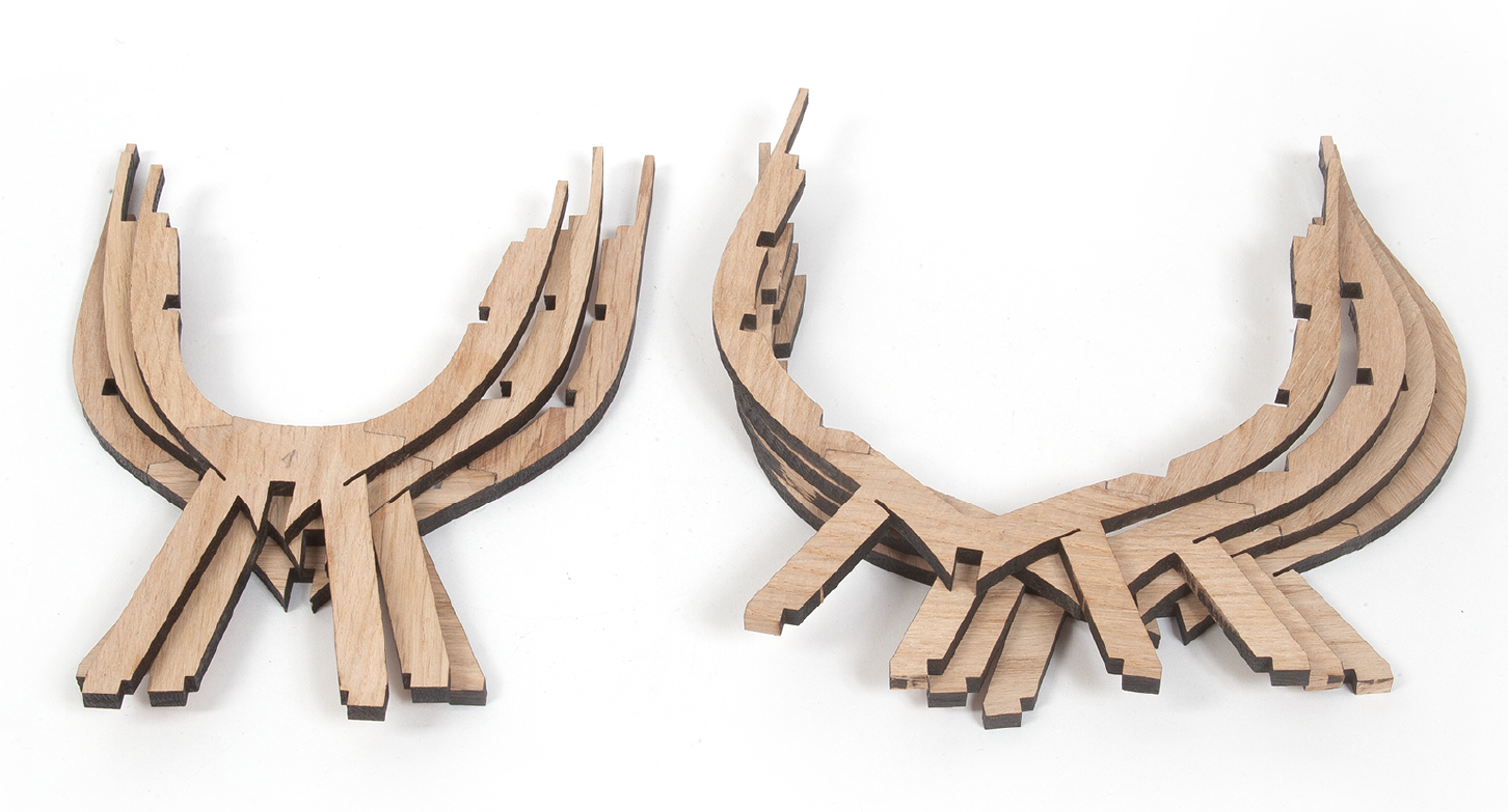
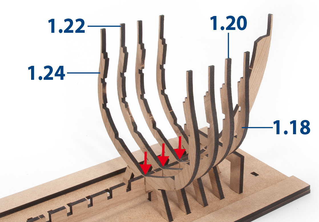
Step 7
In the picture you can see the seven frames built.
Step 8
Insert the keel back into the construction base and immobilise it. Apply white glue to the fourth vertical groove of part 1.1, where frame 4 will make contact.
Step 9
Insert frame 4 so that it fits into the groove in the false keel and into the mounting base. The frame should be glued to the false keel, but not to the base.
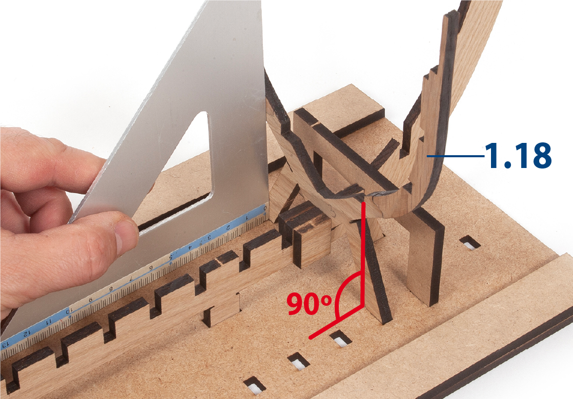
Step 10
Use a set-square to check that the frame forms a 90º angle with the base.
Step 11
Repeat the same process to glue and insert frames 5, 6 and 7.
Step 12
Remove part 1.8 from the structure. Then apply white glue to the false keel and insert and glue frames 1, 2 and 3. Keep the parts immobilised on the base until the glue dries.
Step 1
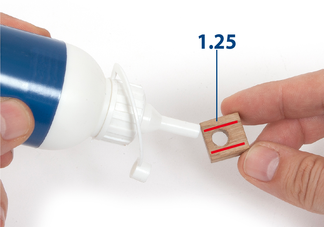
Check the fit of part 1.25 between frames 3 and 4. Sand the part if necessary to fit.

Step 2
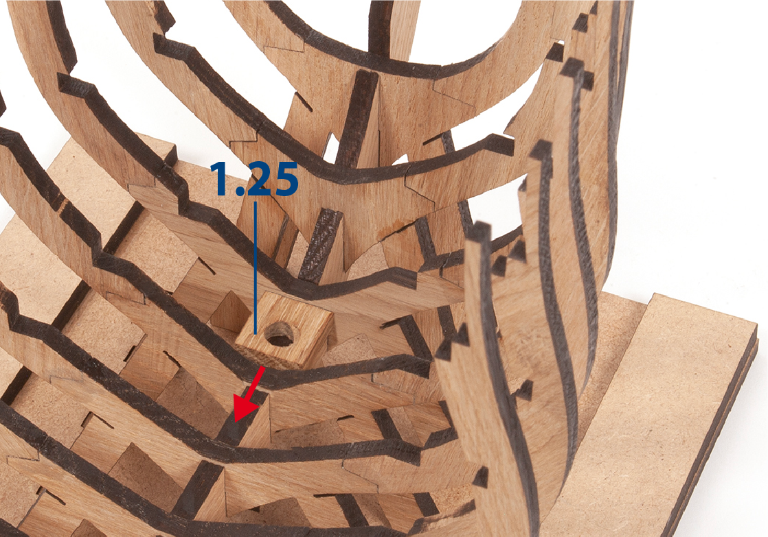
Apply white glue between the red lines on the base of the part and place it centred on the false keel.
Step 3
The hole in part 1.25 should be closer to the rear of the hull as indicated by the red arrow.
Step 4
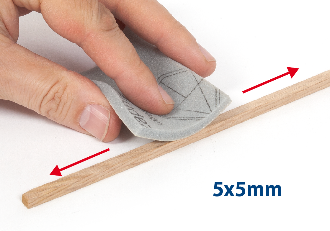
Take a 5x5mm oak strip and sand it with fine-grit sandpaper or sponge-sandpaper.
Step 5
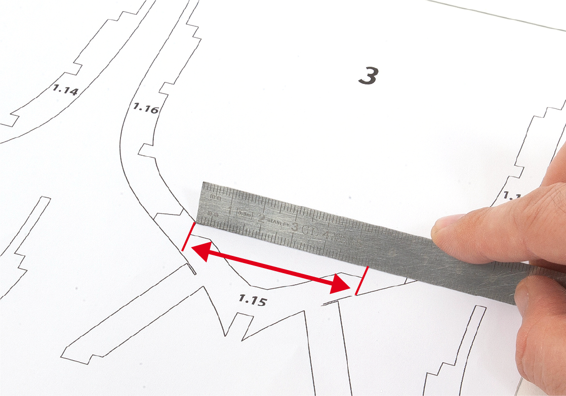
Use a ruler to measure the space inside frame 3, either on the template or on the physical piece.
Step 6
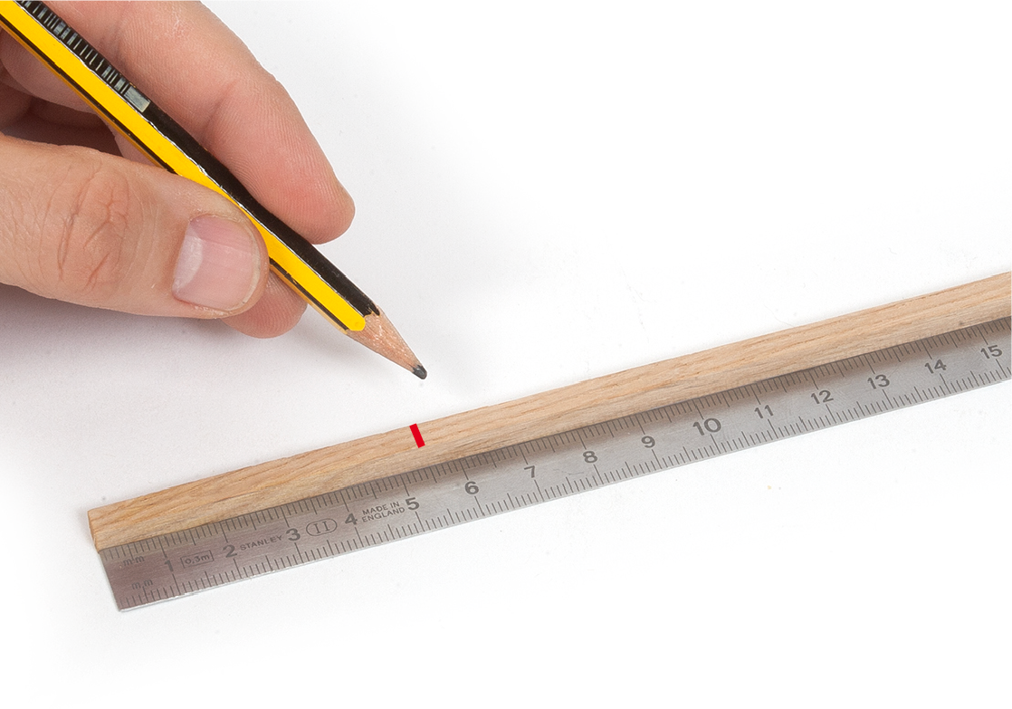
Transfer the measurement to the 5 x 5mm strip.
Step 7
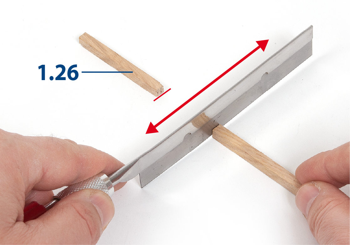
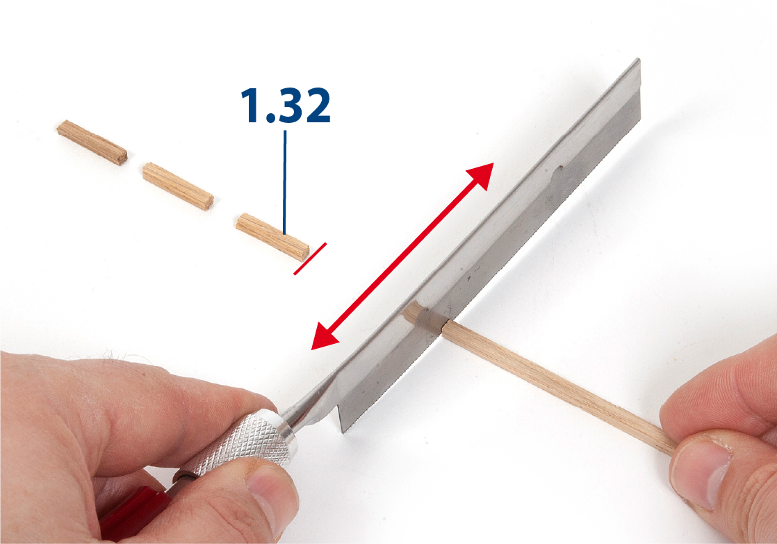
Use a hacksaw to cut part 1.26 to length.
Step 8
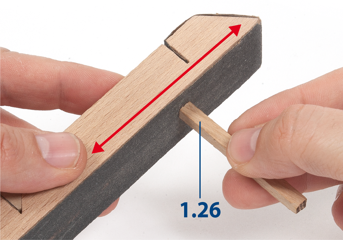
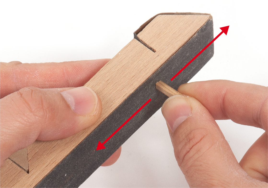
Use a sanding block or flat file to smooth both ends of the workpiece.
Step 9
Check the fit of the part on the template for frame 3.
Step 10
Following the same procedures, make parts 1.27 to 1.30, measuring between frames 4, 5, 6 and 7.
Step 11
Apply white glue to the ends of part 1.26.
Step 12
Insert and glue piece 1.26 on the inside of frame 3, between its lower recesses. Proceed in the same way to glue pieces 1.27 and 1.28 in the following frames.
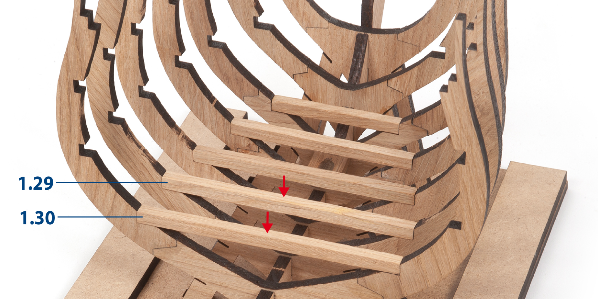
Step 13
Repeat the same process to insert and glue parts 1.29 and 1.30. Keep the parts immobilised until the adhesive dries.
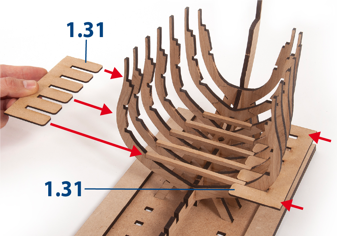
Step 1
Insert, without gluing, pieces 1.31 (REFERENCE 2001-5), one on each side of the frame. These pieces will help to keep the frames parallel to each other.
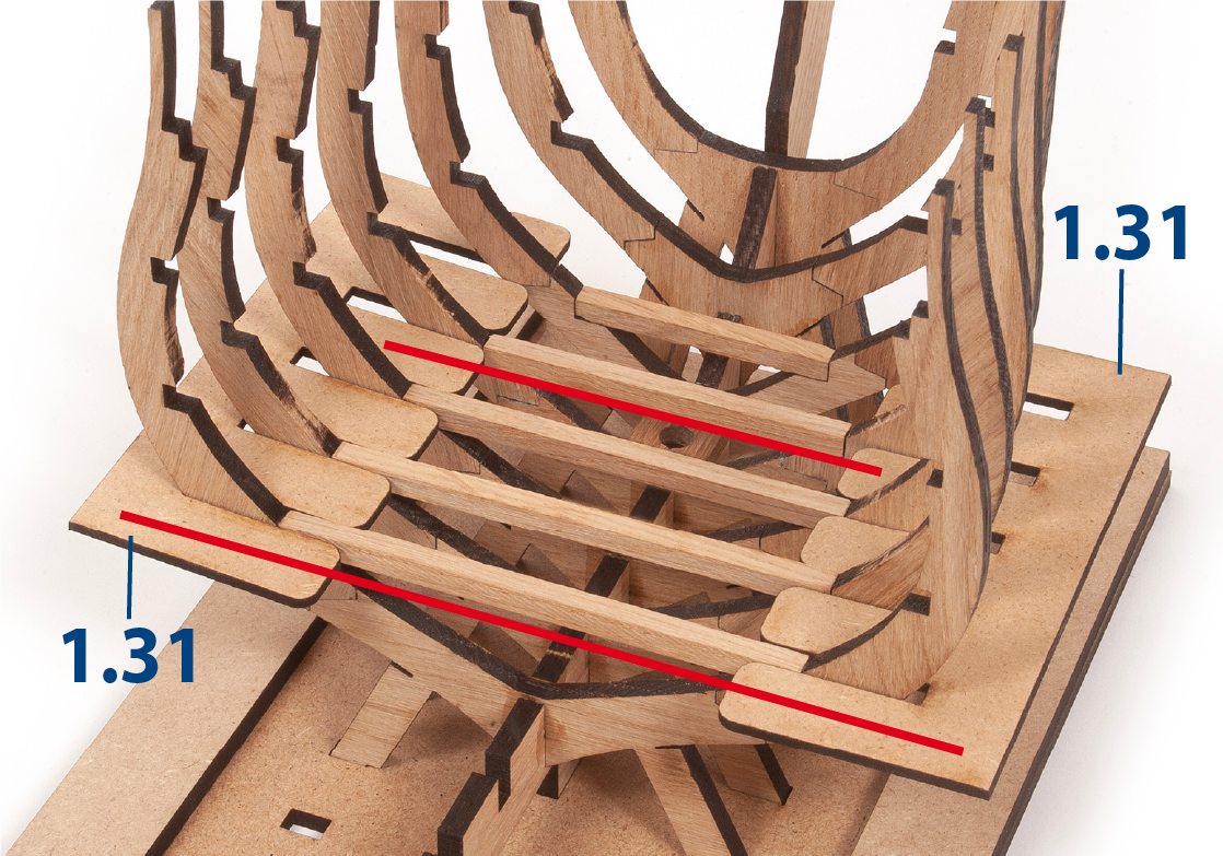
Step 2
Keep the parts 1.31 inserted in the frames and in a horizontal position.
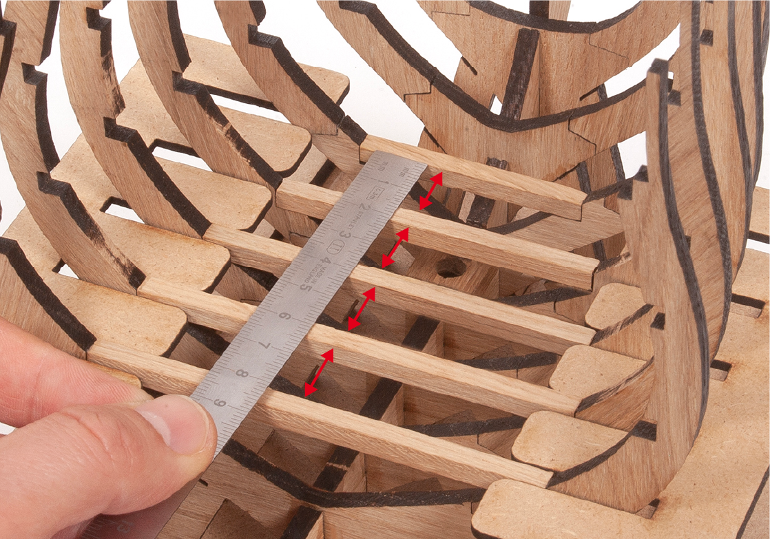
Step 3
Use a ruler to measure the space between the frame rails.
Step 4
Sand a 3 x 3mm strip of limewood with fine-grit sponge-sandpaper.
Step 5
Cut the parts 1.32 to the measurement obtained in step 3.
Step 6
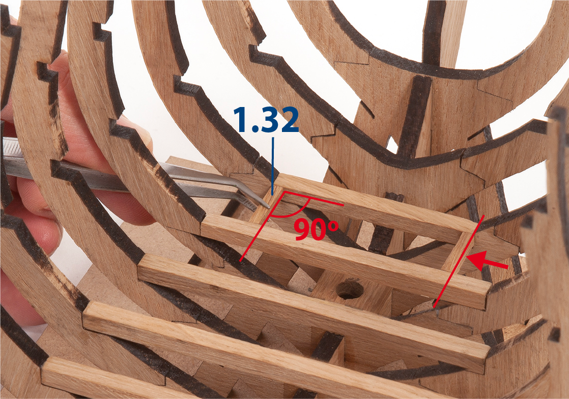
Check the fit of two pieces 1.32 between the frames are flush with the ends of the batten of the first frame. They must form a 90° angle.
Step 7
Use a sanding block or flat file to adjust the ends of the parts 1.32.
Step 8
Apply white glue, or super glue if preferred, to the ends of the parts 1.32.
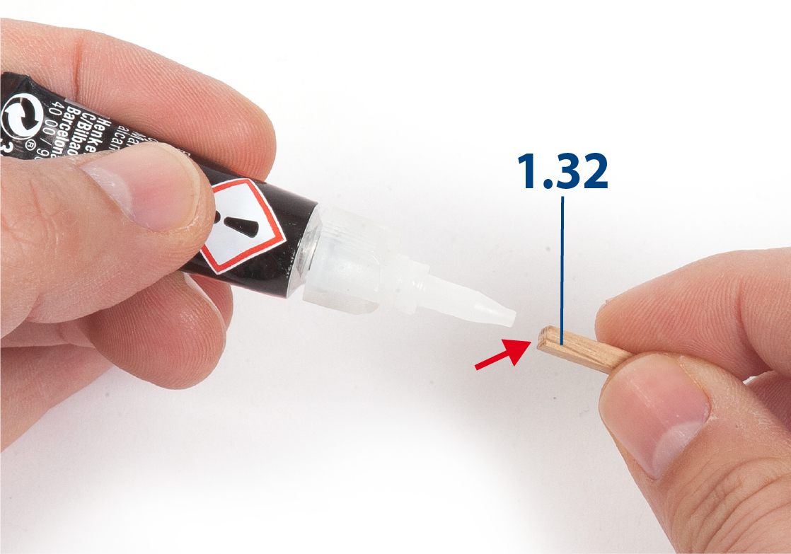
Step 9
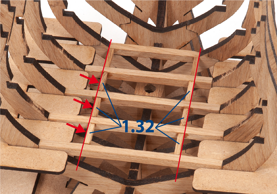
Insert and glue two 1.32 pieces so that they are flush with the top of the frame rails. Glue six more 1.32 pieces.
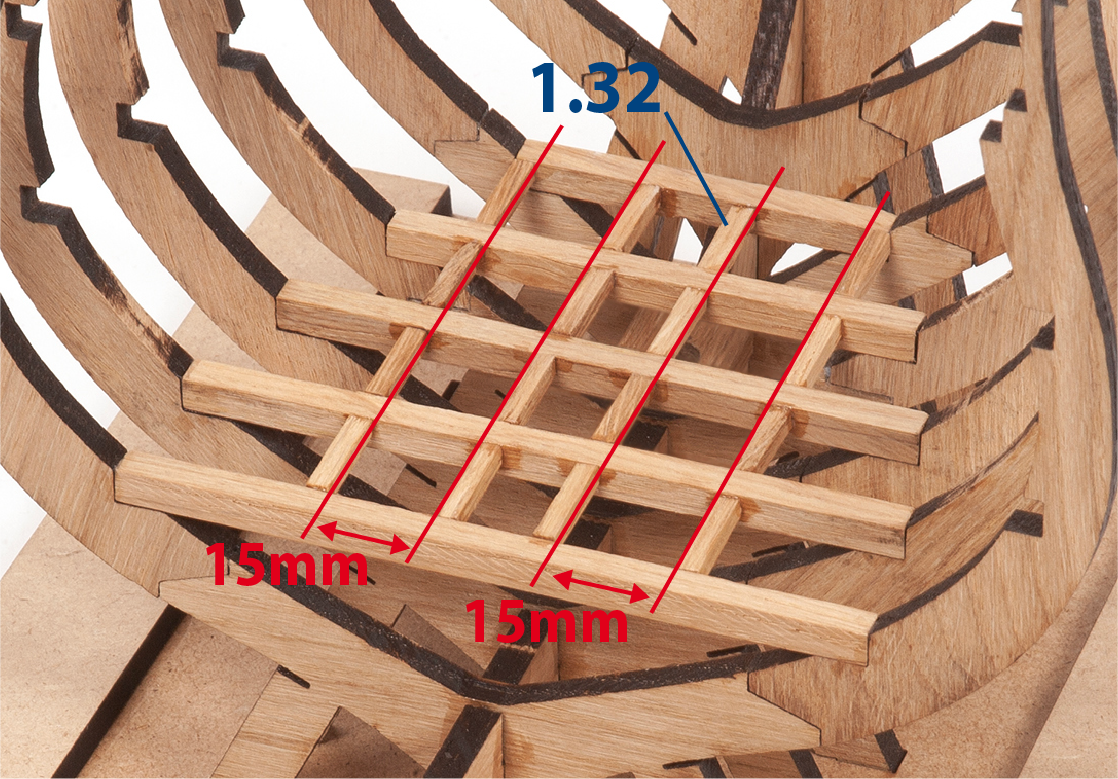
Step 10
Make and glue eight more 1.32 pieces at the distances indicated in the image.
Step 11
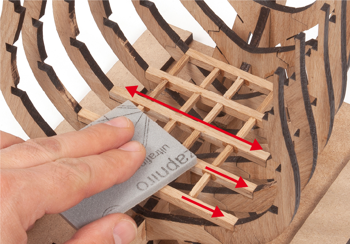
Sand the surfaces of the parts and remove the resulting dust.
Step 12
Apply colourless varnish to the structure, as you will not be able to access it with a brush later on. Do not apply varnish to the inside of the frame rabbets (notches in the frames). It is also not necessary to apply varnish to the legs of the frames, nor to the mounting base.
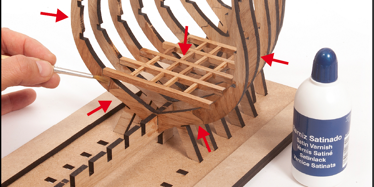
Step 13
In the picture you can see how the structure should look once varnished.
