Pack 2
BUILD INSTRUCTIONS
Instructions for building your USS Constitution model ship
Your model of the USS Constitution is divided into 12 packs.
You will need to follow the step-by-step assembly photos, the plans and the explanatory texts below.
Please save the leftover materials from each pack for use when instructed to do so at a later stage of the assembly instructions.
The IP sheets displayed below are drawings of laser-cut parts and photo-etched brass parts and will serve as a guide for identification of some parts.
Use the PARTS REFERENCE table to help locate the parts.
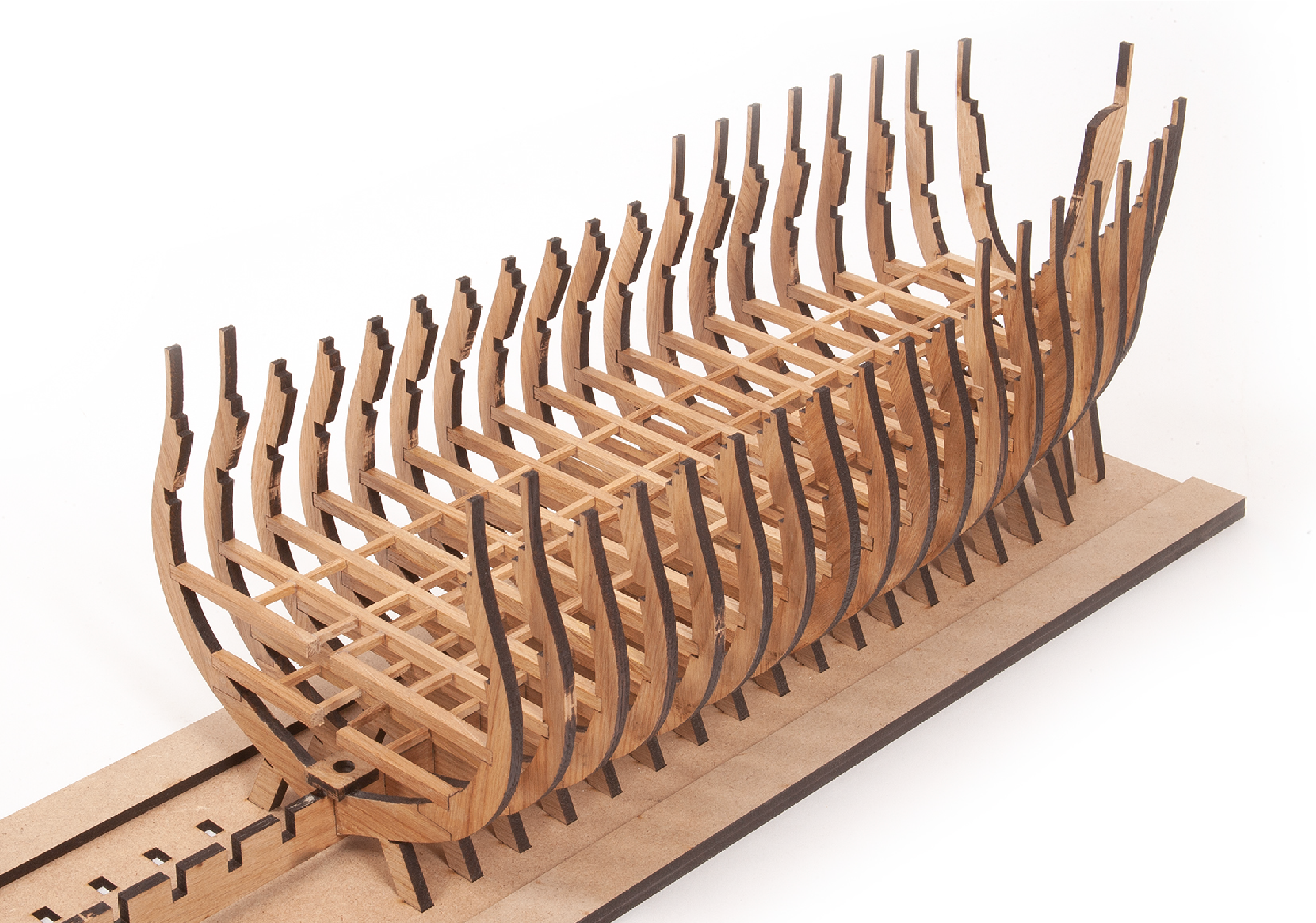
The PL-00 templates (printed at 1/1 scale) included in each pack will serve as a guide for building the frames.
Please check the list below to ensure you have all the tools required for building your wooden ship.
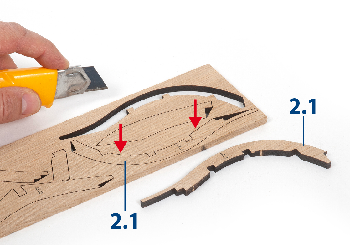
When removing a part, cut the ribs that join the part to the wooden plate with a cutter.
Remove the parts carefully so as not to break them.
Keep and store the parts in their frames. Only remove the parts you are working on in each step.
Extra support can be found on our forum or from the Expert Directory page of our website.
PARTS LIST
| Material | Quantity | |
| Boards 2001-10 – 2001-16 | Wood | 7 |
| Wooden Strips | ||
| 5 x 5 x 400 mm | Oak | 14 |
| 3 x 3 x 400 mm | Lime wood | 7 |
| 2 x 3 x 600 mm | Lime wood | 5 |
| Rod Diameter 10 mm x 450 mm | Mahogany | 1 |
| Templates | ||
| Assembly template PL-03 | 1 | |
| Assembly template PL-04 | 1 | |
| Assembly template PL-05 | 1 |
Tools you will need: cutting mat, pencil, cutting knife, fine-grit sandpaper or sponge sandpaper, file, white wood glue, super glue (cyanoacrylate glue), masking tape, set square, hacksaw, sanding block, 30 cm steel ruler, clamp
PACK 2 IDENTIFICATION SHEETS
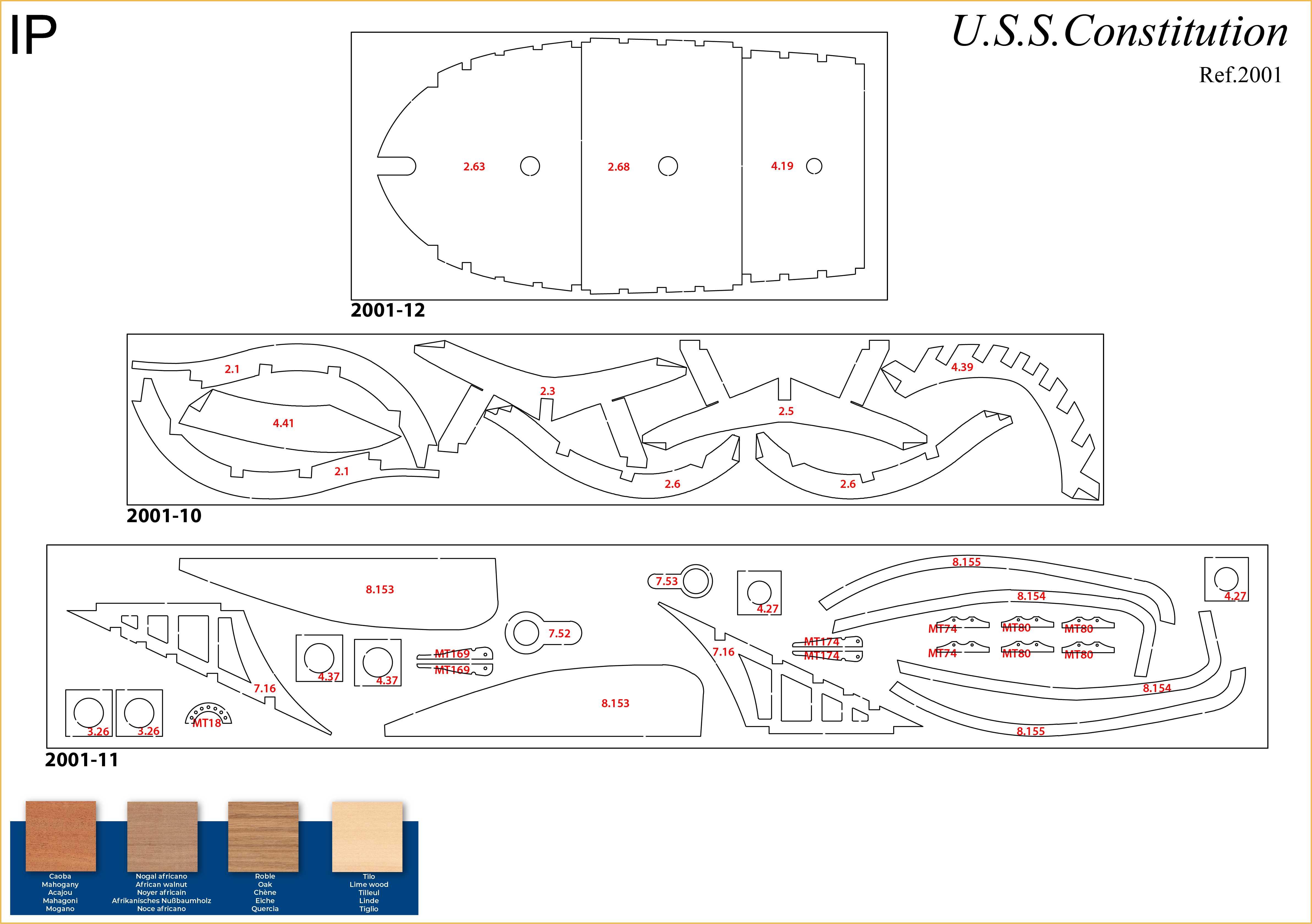
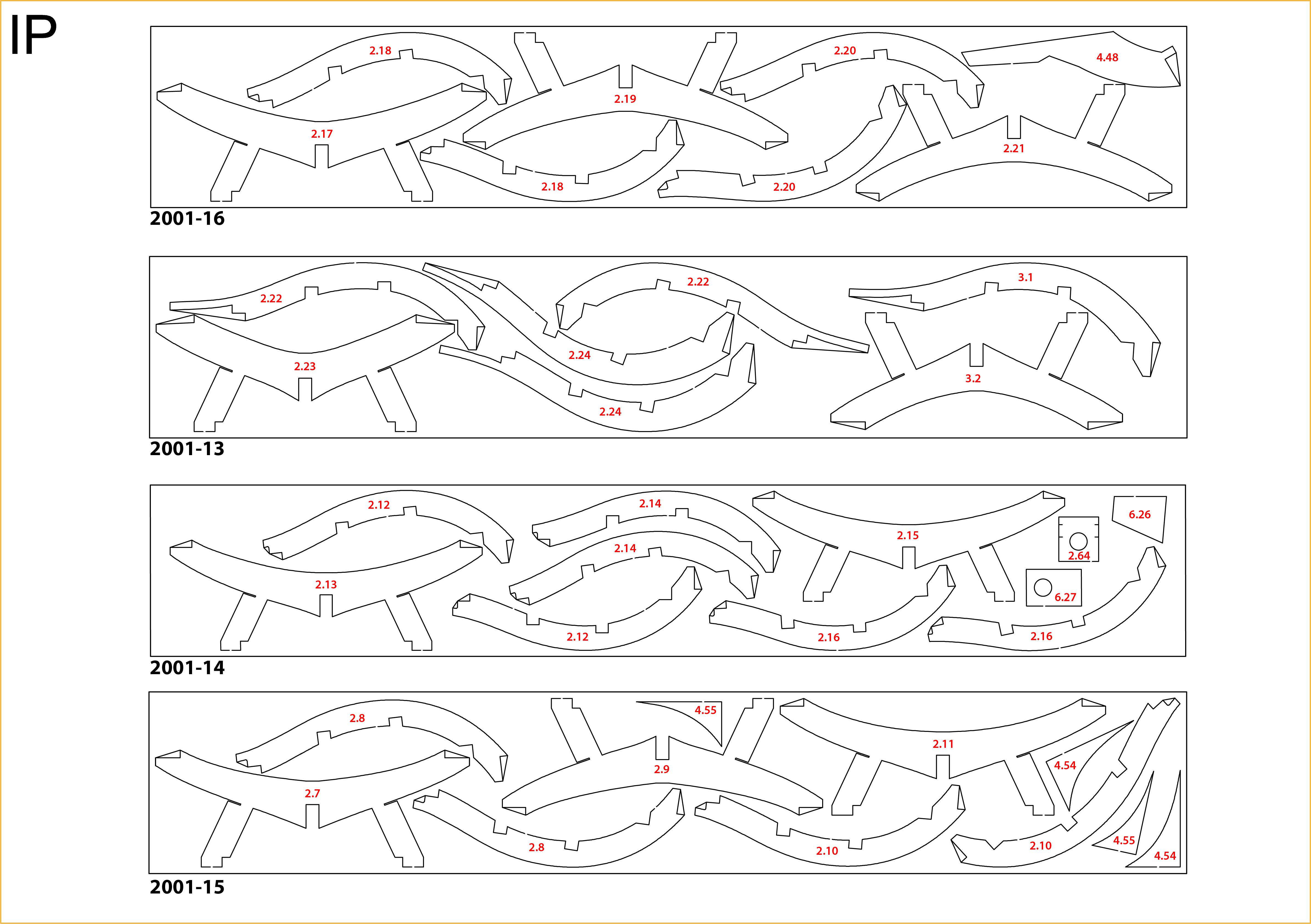
PARTS REFERENCE
PART NO. | IP-SHEET LOCATION | PART NO. | IP-SHEET LOCATION | PART NO. | IP-SHEET LOCATION |
| 2.1 | 2001-10 | 2.10 | 2001-15 | 2.19 | 2001-16 |
| 2.2 | 2001-7 | 2.11 | 2001-15 | 2.20 | 2001-16 |
| 2.3 | 2001-10 | 2.12 | 2001-14 | 2.21 | 2001-16 |
| 2.4 | 2001-6 | 2.13 | 2001-14 | 2.22 | 2001-13 |
| 2.5 | 2001-10 | 2.14 | 2001-14 | 2.23 | 2001-13 |
| 2.6 | 2001-10 | 2.15 | 2001-14 | 2.24 | 2001-13 |
| 2.7 | 2001-15 | 2.16 | 2001-14 | 2.56 | 2001-5 |
| 2.8 | 2001-15 | 2.17 | 2001-16 | 2.63 | 2001-12 |
| 2.9 | 2001-15 | 2.18 | 2001-16 | 2.68 | 2001-12 |
Step 1
Use a pencil to transfer the numbers from the IP sheets (PACK 2 IDENTIFICATION SHEETS above) to the wooden boards.

Step 2
Cut the ribs that join the pieces to the boards with a cutter, so that you can remove the pieces without damaging them. You will need to recover parts from the previous pack in order to continue building the frames.
Step 3
Place the parts on a flat surface and sand them with fine-grit sandpaper or sponge-sandpaper.
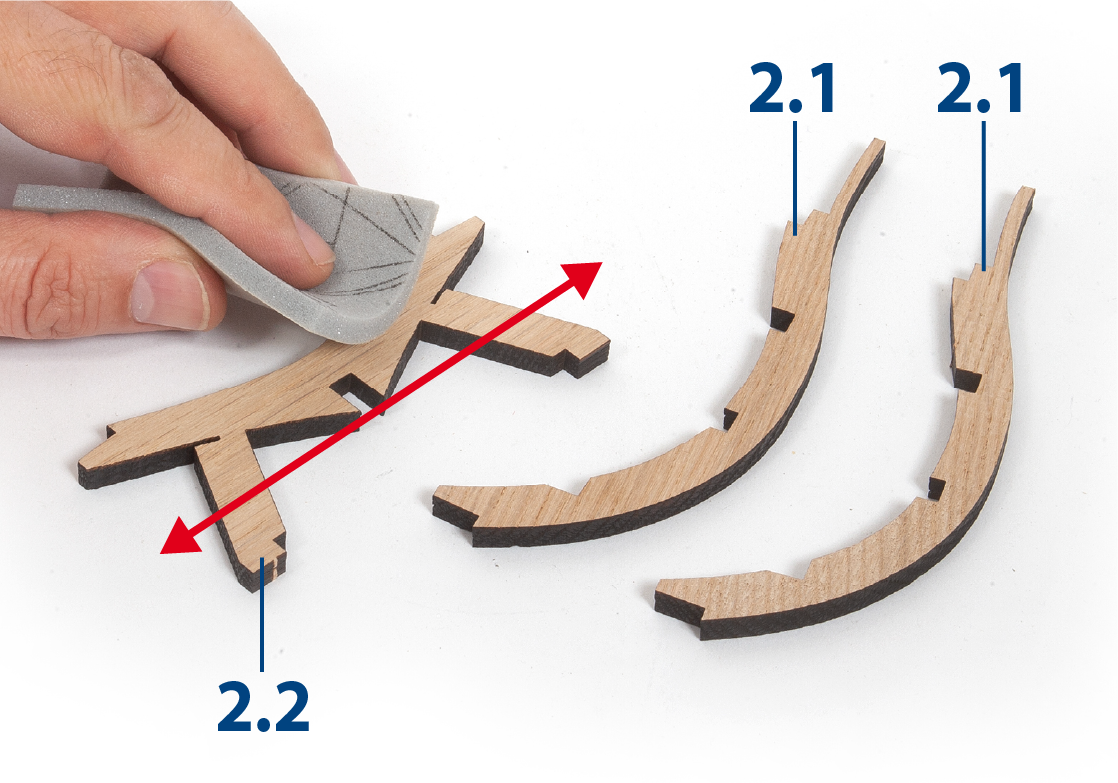
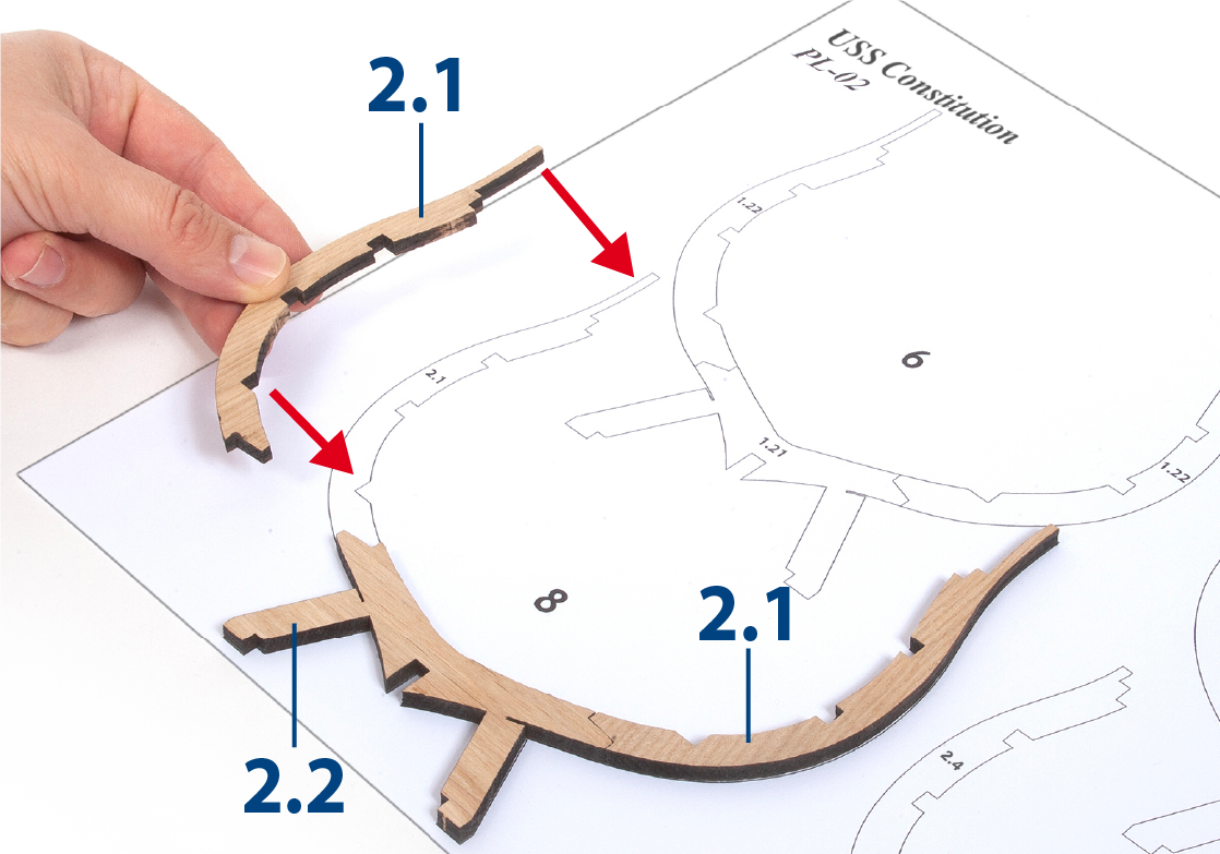
Step 4
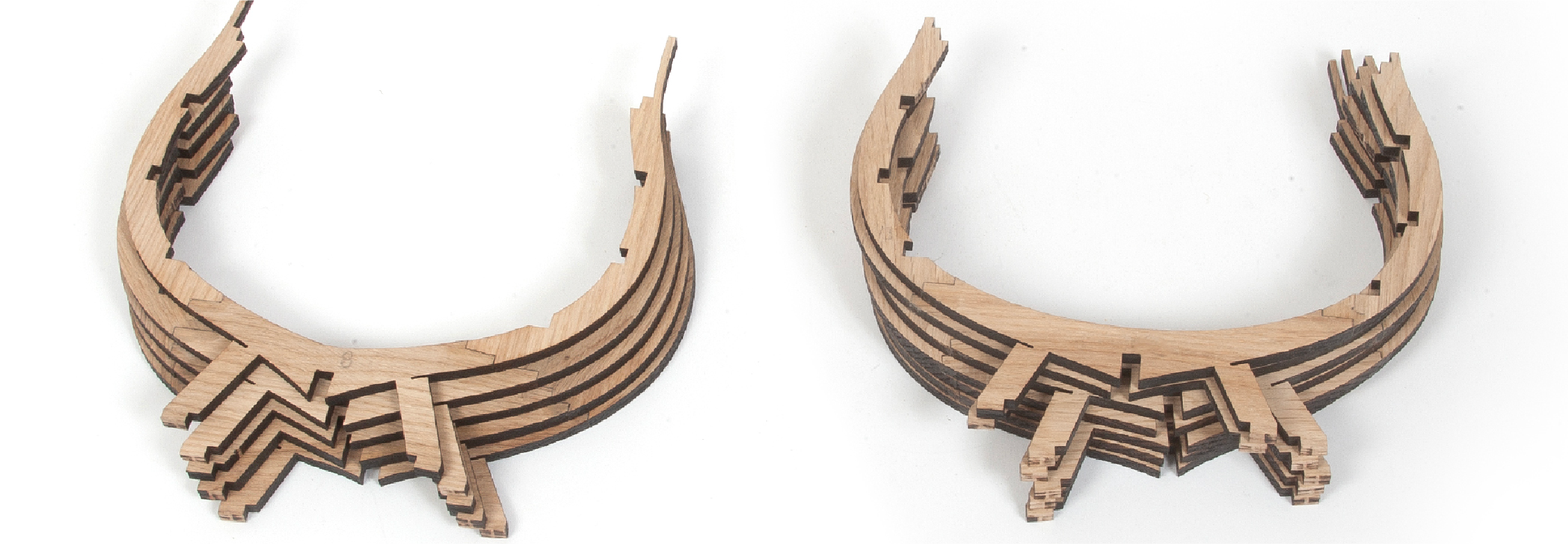
Check how the pieces fit together to form frames 8 and 9 on template PL-02.
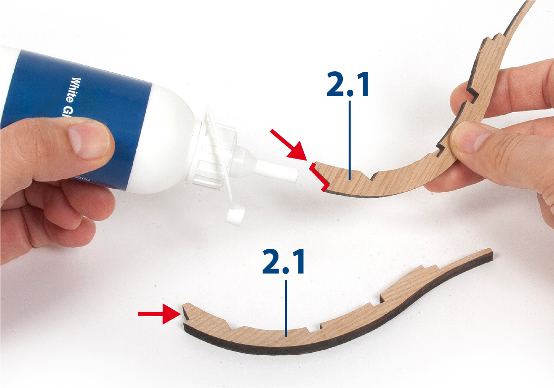
Step 5
Apply white glue to the ends of parts 2.1.
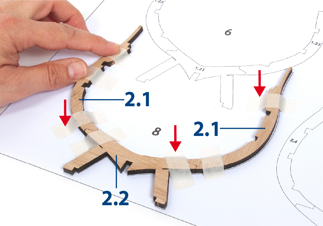
Step 6
Glue the pieces together to form frame 8. Use masking tape (painter's tape) to secure the pieces to the template until the glue dries.
The pieces should be glued together, but should not be glued to the template. Cover the template with cling film to stop the parts from sticking to the template.
Step 7
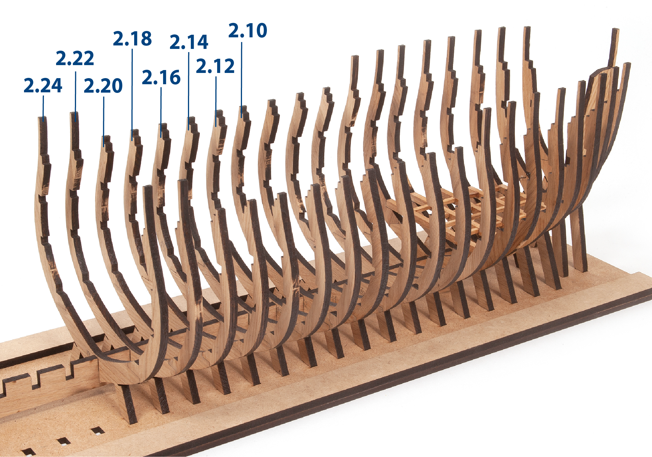
Follow the same procedures to check and build frames 9 to 19. Go over the frames with a fine-grit sponge sander to remove any glue or paper that may have stuck to them.
Step 8
Check the fit of frame 8 on the keel and on the mounting base. Remove the frame and apply glue to the areas where it will contact the keel.

Step 9
Re-insert the frame until it butts against the keel and base.

Step 10
Check that the frame forms a 90° angle with the base. Immobilise the part until the glue dries.

Step 11
Following the same processes, insert and glue frames 9 to 11.

Step 12
Continue inserting and gluing frames 12 to 19. It is important to work on the mounting base at all times to align the frames correctly and avoid breakage.
Step 1
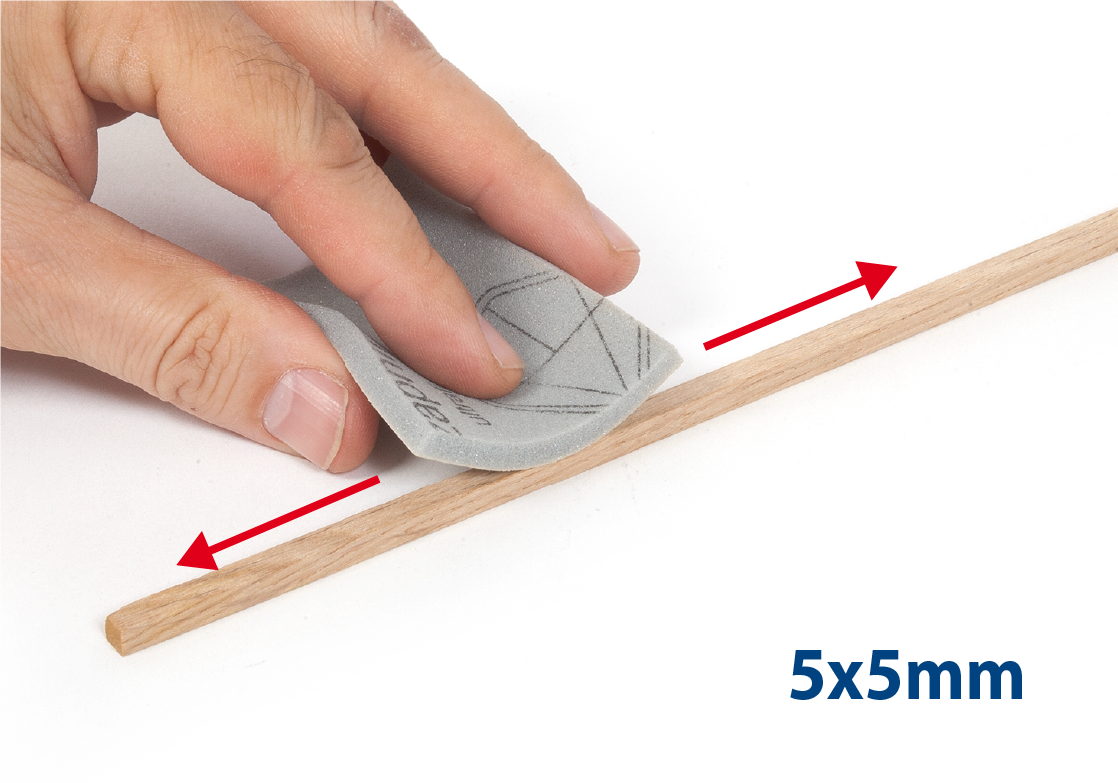
Take a 5x5mm oak strip and sand it with fine-grit sandpaper or sponge-sandpaper.
Step 2
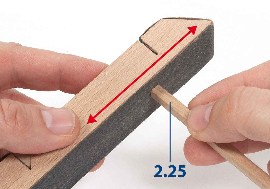
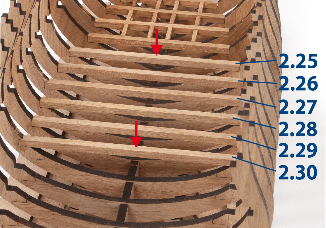
Use a ruler to measure the space inside frame 8. Use a saw to cut the 2.25 piece to size.

Step 3
Go over both ends of the workpiece with a sanding block.
Step 4
Apply white glue to the ends of part 2.25.

Step 5
Insert and glue piece 2.25 on the inside of frame 8, between its lower recesses. Proceed in the same way to make and glue pieces 2.26 to 2.30 in the following frames.
Step 6
Repeat the same process to make and glue parts 2.31 to 2.36. Keep the parts immobilised until the adhesive dries.

Step 7
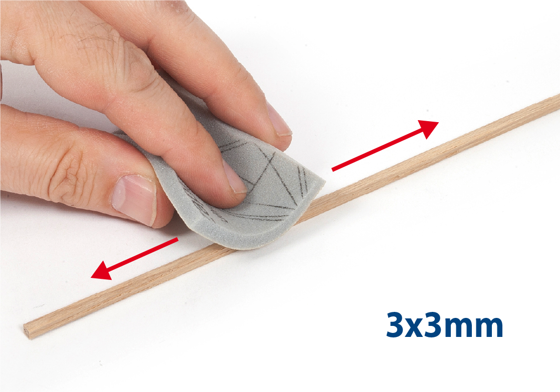
Take a 3x3mm strip of lime wood and sand it with fine-grit sandpaper or sponge-sandpaper.
Step 8
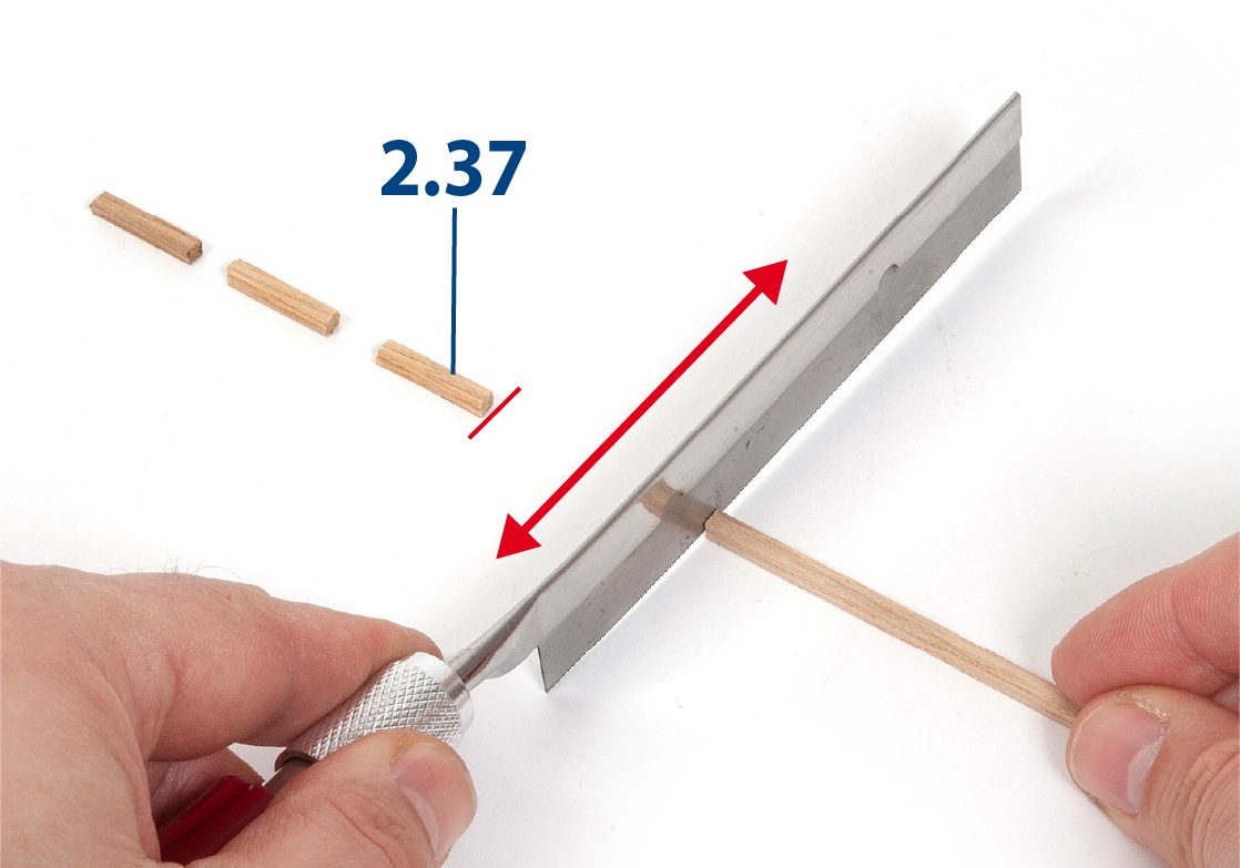
Cut to length parts 2.37 and go over the ends with a sanding block.
Step 9
Place pieces 1.31 on both sides of the structure to keep the frames parallel at all times.

Step 10
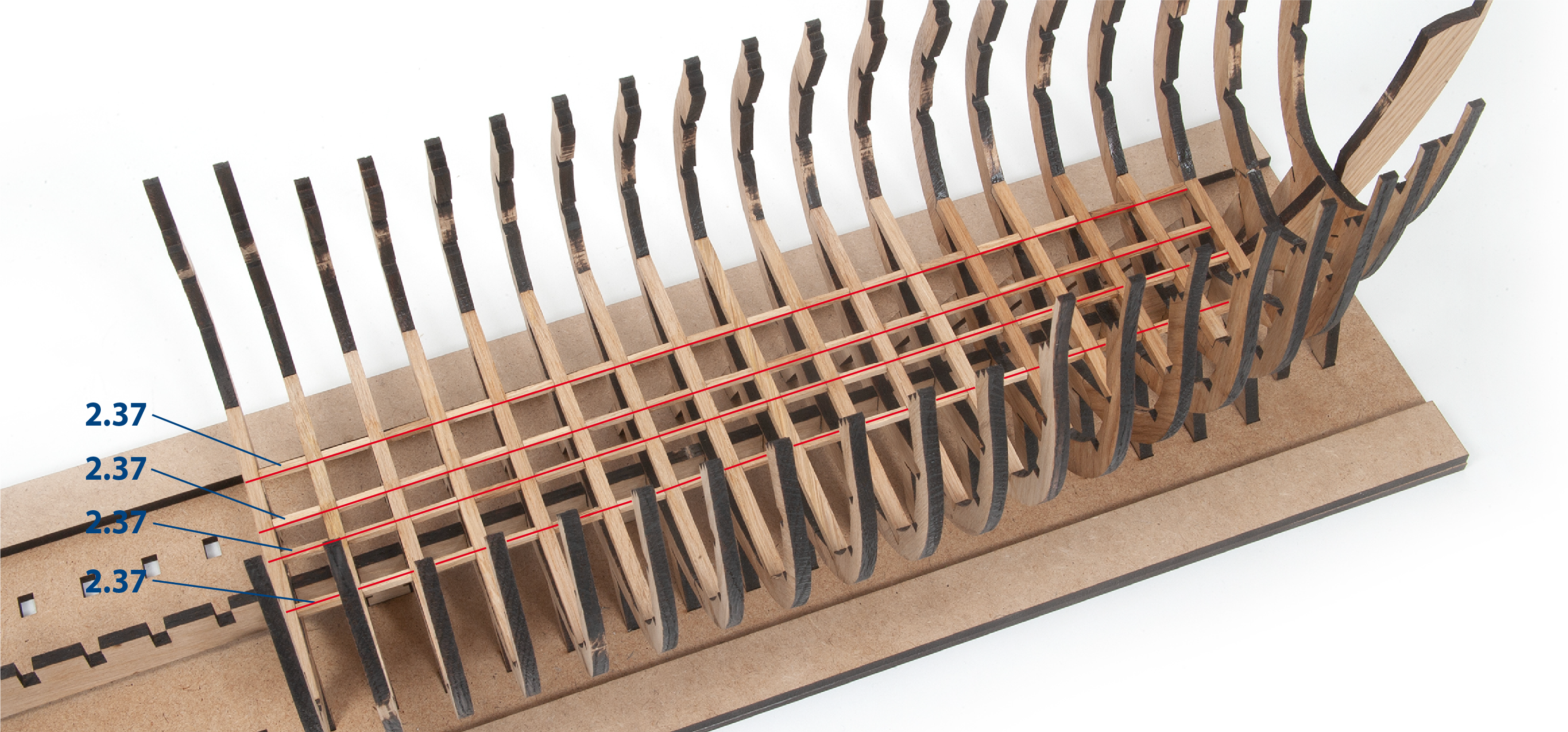
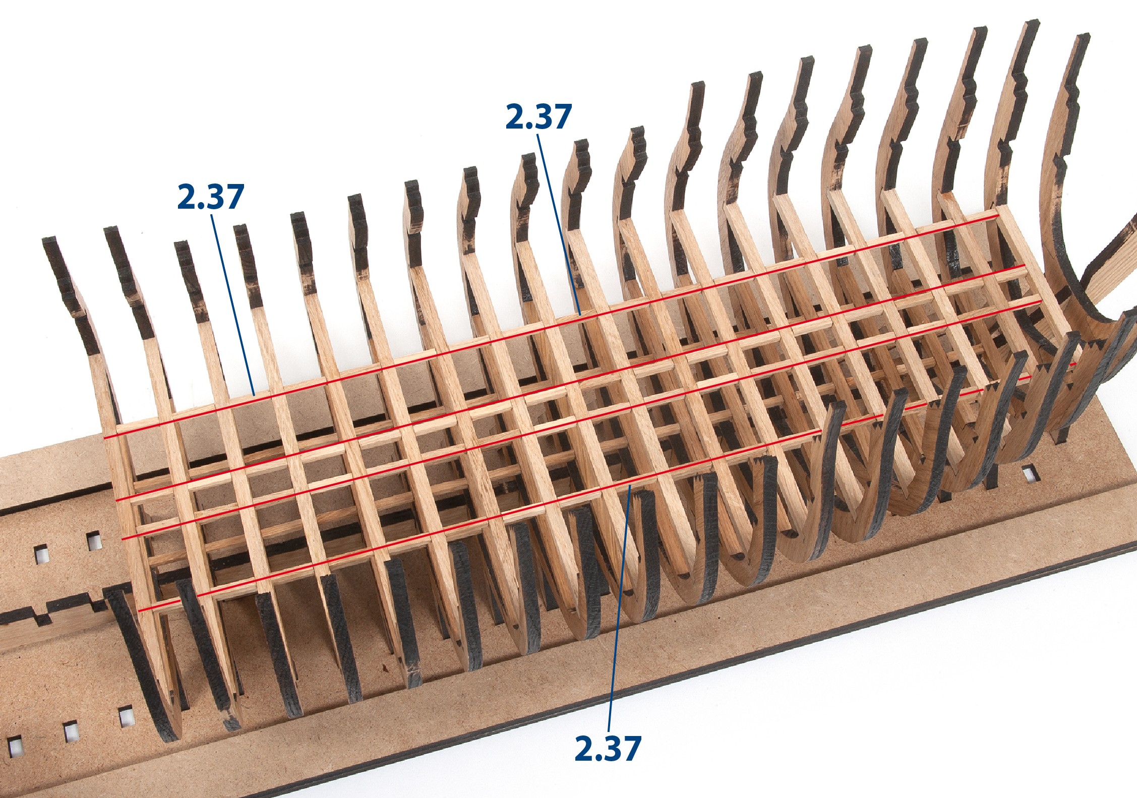
Glue parts 2.37 after the parts you glued at the front of the structure. To achieve a good alignment, you can use a ruler and secure it with masking tape.

Step 11
Continue placing pieces 2.37 until all four rows are completed.
Step 1
Use a fine-grit sponge-sandpaper to remove any unevenness or rough spots on the wood. Then remove any dust resulting from sanding.
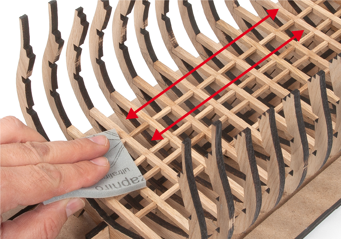
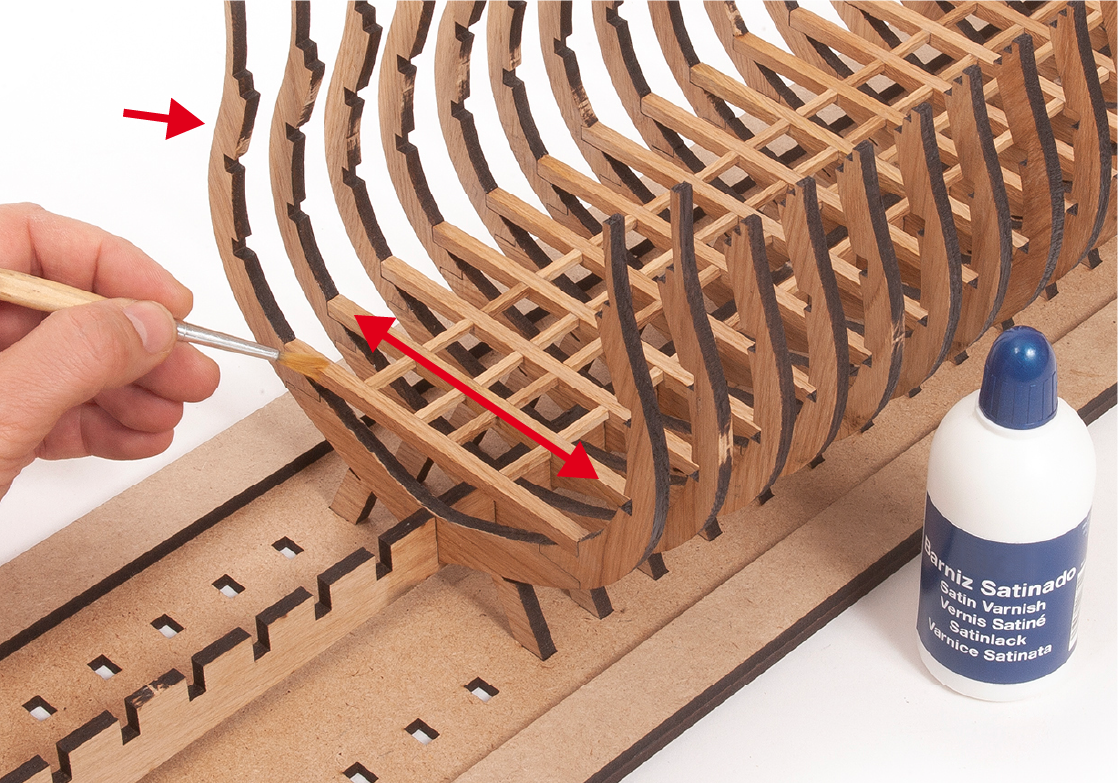
Step 2
Apply varnish to all the wooden parts you have added to the structure.
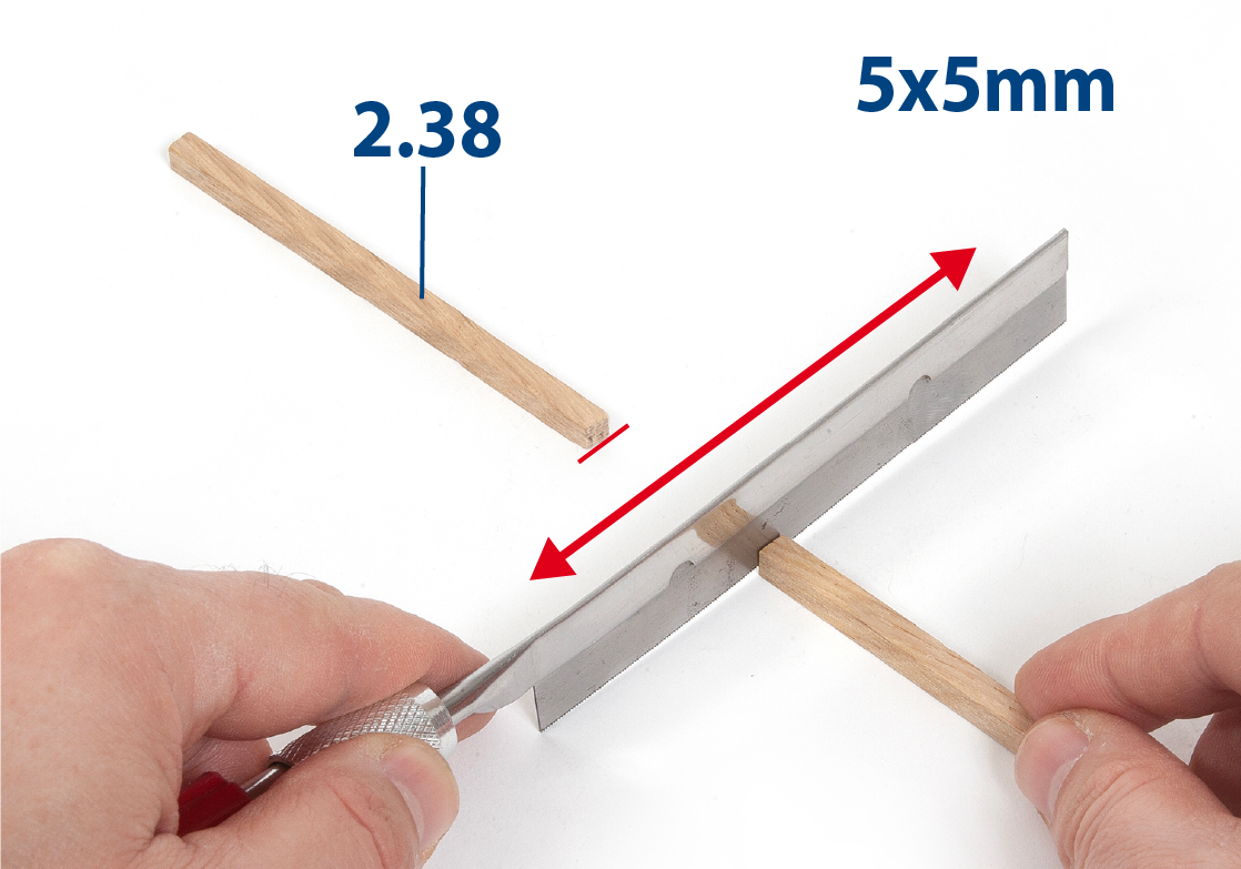
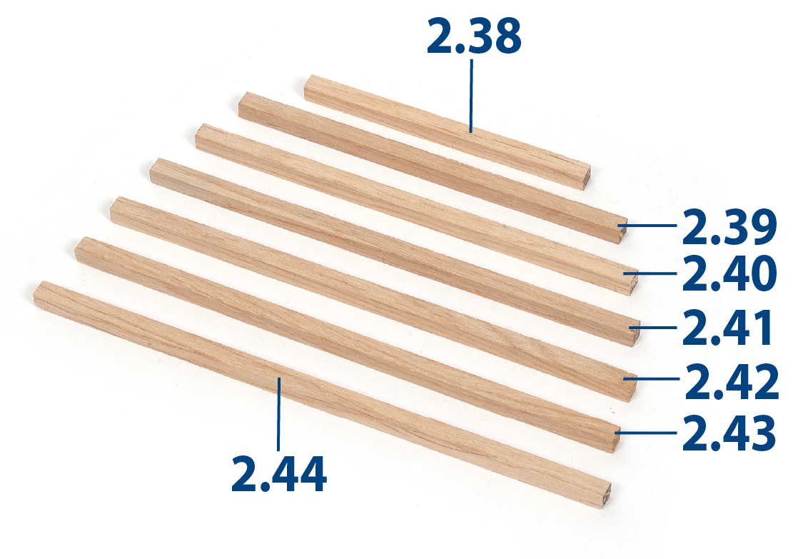
Step 3
Use 5x5mm oak strips to cut the 2.38 pieces to size.
Step 4
Cut to length parts 2.39 to 2.44.
Step 5
Apply glue and glue the parts into the lower recesses of the frames. Also glue parts 2.45 to 2.51.

Step 6
Cut to length and glue pieces 2.52 to 2.55.

Step 7
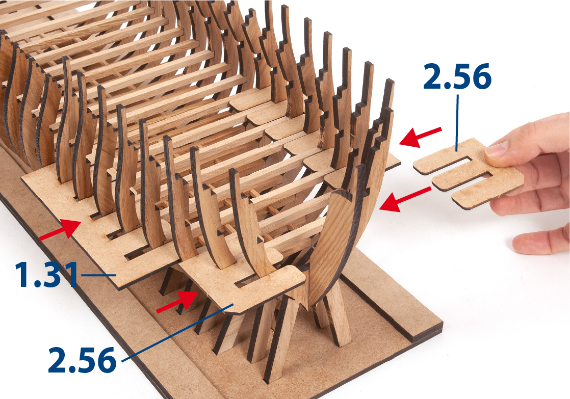
Insert, without gluing, parts 1.31 and 2.56.
Step 8
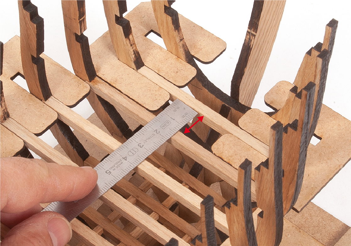
Measure the space between frame rails 2 and 3.
Step 9
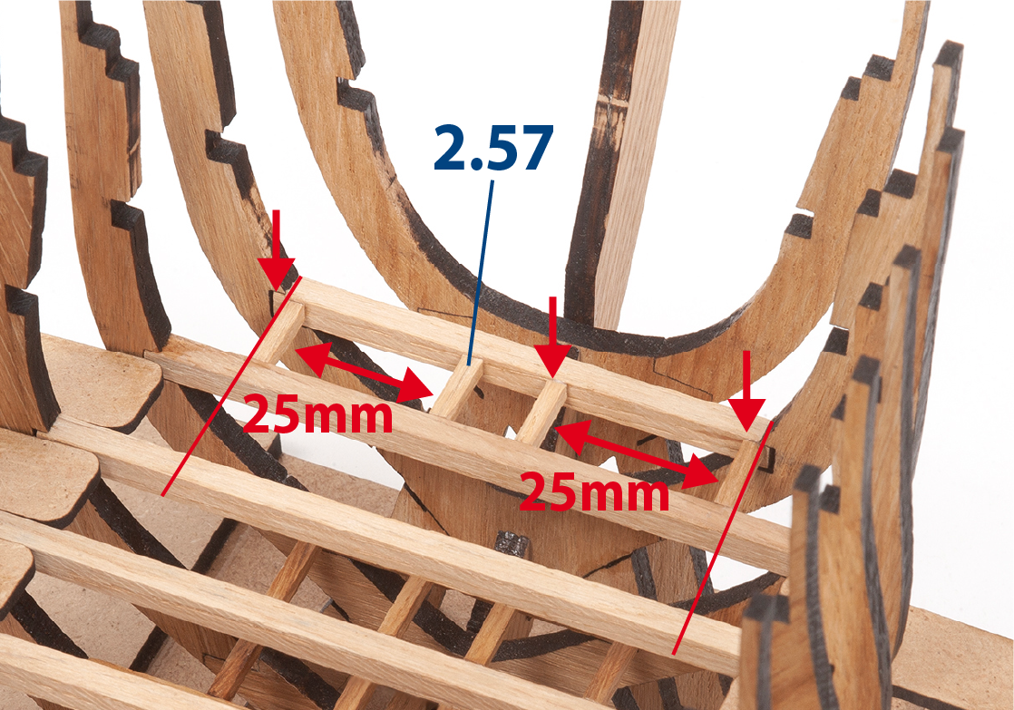
Cut to length and glue parts 2.57 between rails 2 and 3.
Step 10
Cut parts 2.37 to length and glue them.
Step 1
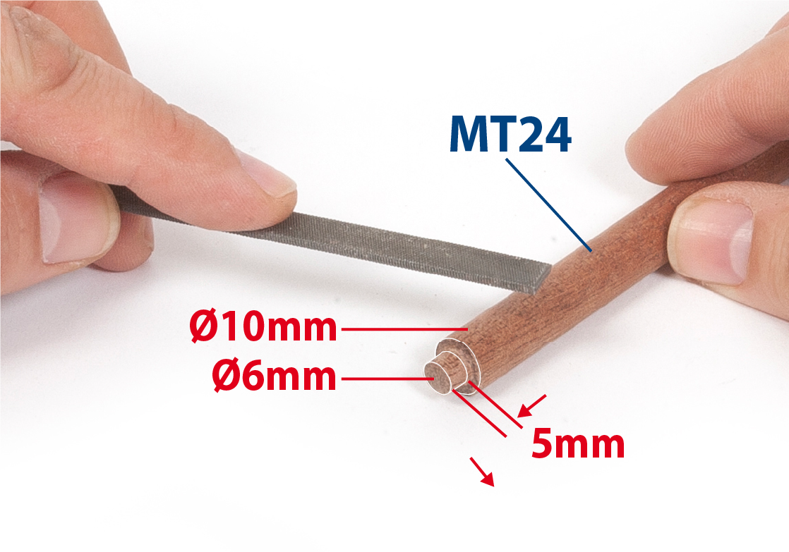
Take a ø10mm rod and at one end reduce its diameter to ø6mm. Use a flat file and pass it back and forth over the rod, applying pressure, to reduce its diameter.
Step 2
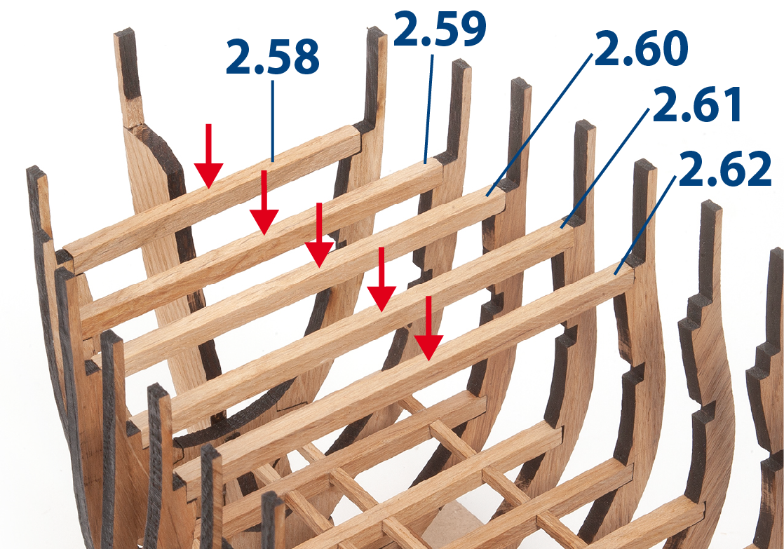
Cut pieces 2.58 to 2.62 (5x5mm strips) to size.

Step 3
Present the pieces on the upper recesses of the first 5 frames, without gluing them.
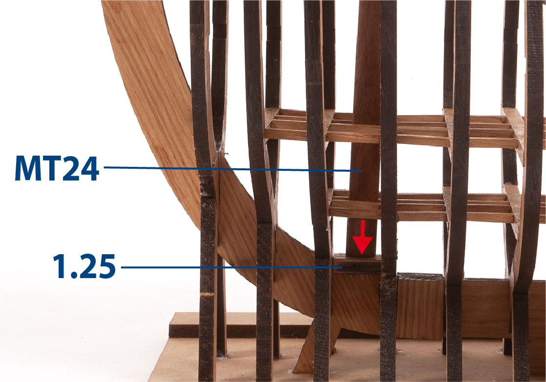
Step 4
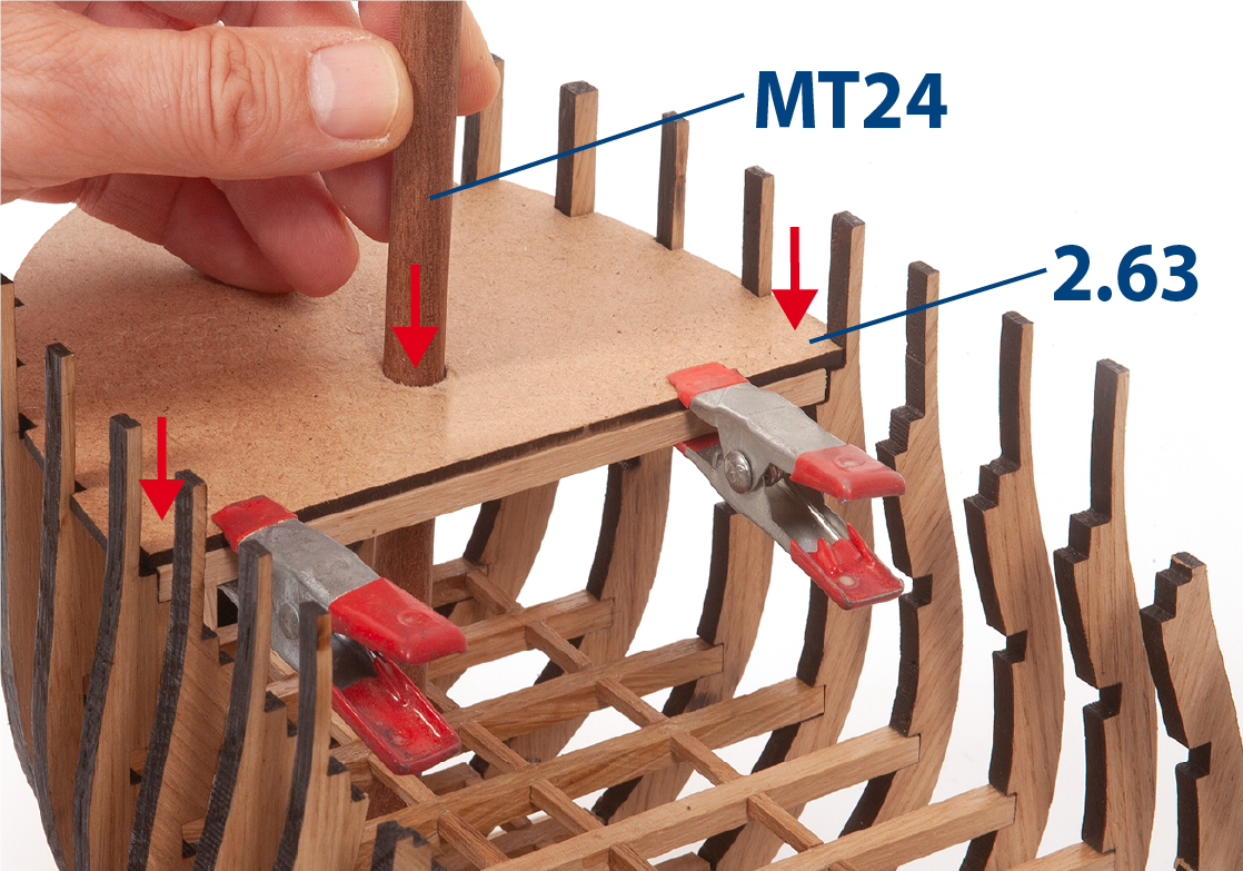
Position part 2.63 between the frames and on the battens. Insert the part carefully to avoid breaking the frames. These parts must not be glued. Insert part MT24 to check its fit in part 1.25.
Step 5
Remove parts and battens and touch up with a file.
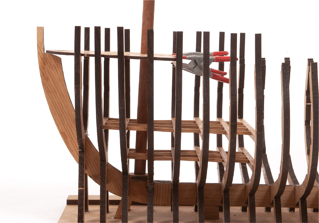
Step 6
Observe in the picture how the parts must match.
Step 7
Observe the fit of the parts in the picture. Afterwards, remove the parts and set them aside.
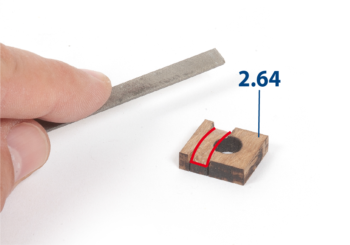
Step 8
Retouch part 2.64 so that it can fit into frame 19.
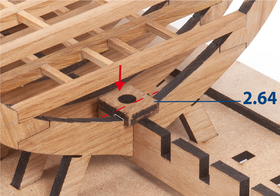
Step 9
Apply glue and glue the piece with its hole in front of the frame.
Step 10
Cut to length pieces 2.65 to 2.67 and place them in the upper recesses of frames 17 to 19, without gluing them.

Step 11
Position part 2.68 between the frames and on the battens. Insert it carefully so as not to break the frames.
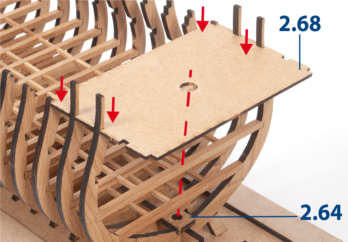
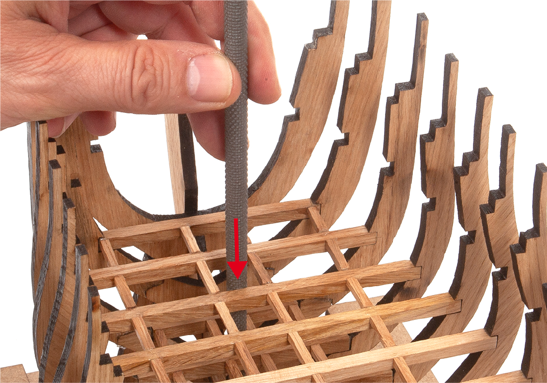
Step 12
Insert part MT24 to see how it fits into part 2.64. Touch up any parts that interfere with the path of the MT24 with a circular file. Afterwards, remove the parts and save them for later use.

Step 13
Observe in the image how the lowered battens should look. Apply varnish to all the pieces you have added to the structure.